CP-6-series Mechanical Reference.pdf - 第34页
1. Machine Components 1.1 Front View of the Machine <CP-6, CP-6M, CP-642, CP-642M, CP-643E, CP-643ME, CP-65> <CP-652C> Servo box 2 Servo box 3 Servo box 1 XY-table Control box 1 Control box 2 Out-conveyor Bre…

Part 1
Introduction
1. Machine Components
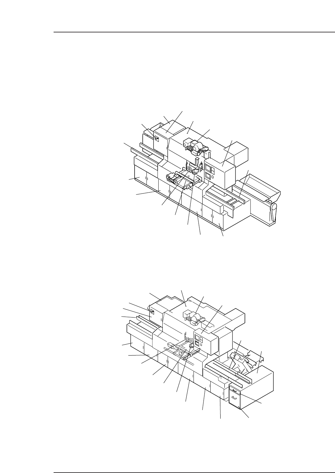
1.1 Front View of the Machine
<CP-6, CP-6M, CP-642, CP-642M, CP-643E, CP-643ME, CP-65>
<CP-652C>
Servo box 2
Servo box 3
Servo box 1
XY-table
Control box 1
Control box 2
Out-conveyor
Breaker
In-conveyor
Placing head
Operation panel 1
Mark read camera
Index unit
Cam box
Oil cooler
Transformer box
Waste tape box
Filter
Noise reduction box
CP6M1002Ea
Power box
Servo box 2
Servo box 1
XY-table
Control box 1
Control box 2
Out-conveyor
Breaker
In-conveyor
Placing head
Operation panel 1
Mark read camera
Index unit
Cam box
Oil cooler
CP6M1001Ea
Power box
Part 1 Chapter 1 Machine Components
Edition 1.1 1-1-1 CP-6-series Mechanical Reference
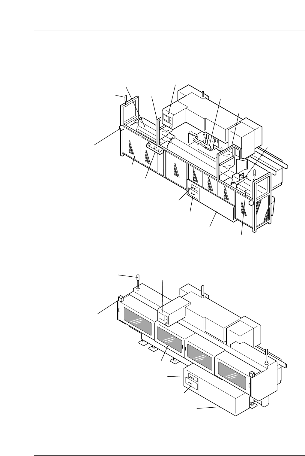
1.2 Rear View of the Machine
<CP-6, CP-6M, CP-642/CP-642M/CP-643E/CP-643ME
(Models with fence), CP-65>
<CP-642/CP-642M/CP-643E/CP-643ME (Models with Rear Cover)>
Operation panel 2
Rear cover
Filter
Waste tape box
Noise reduction box
Note: The waste tape cutter, the device tables 1 and 2
are located on the same positions as for Models with a fence.
CP6M1004Ea
Panel set
complete switch
Panel set complete
signal tower
Device table 1
Operation panel 2
Shutter 1
Waste tape cutter
Shutter 2
Feeder
Rear fence
Operation panel 3
Filter
Waste tape box
Noise reduction box
Device table 2
CP6M1003Ea
Parts set complete
signal tower
Parts set
complete switch
Part 1 Chapter 1 Machine Components
Edition 1.1 1-1-2 CP-6-series Mechanical Reference