CP-6-series Mechanical Reference.pdf - 第5页
About This Manual Edition 1.6 ii CP-6-series Mechanical Reference Page Layout Each page indicates the part number, chapter number and title, section title , manual name, page number, and the edition number of the manual.…

About This Manual
This manual contains important machine maintenance information for the user.
The manual content is intended for specialized technicians who are familiar with the
systems used in this machine.
Please read this manual carefully in order to ensure safe and efficient machine
maintenance.
This manual has been written for all CP-6-series machine types which are listed on the
front cover. Unless otherwise stated, all explanations apply equally to all machines.
Note that all of CP-6-series machine types are distinguished based on differences in the
PCB size that can be handled by the machine. There are two versions; a 4000 type and
5000 type that are derived based on the relevant PCB size.
CP-65E and CP-652CE are 5000 type machines and the others are 4000 type machines.
Keep this manual close to hand when operating the machine.
Manual Structure
This manual consists of the following twelve parts.
Safety Guidelines
Part 1 Introduction
Part 2 Preparation for Production
Part 3 Routine Maintenance
Part 4 Setup
Part 5 Adjustments
Part 6 I/O
Part 7 Proper Data Measurements
Part 8 Pallet Feeder
Part 9 Carrier Type Loading System
Part 10 Supplementary Information
Appendix Electronic Temperature Controller
About This Manual
Edition 1.6 i CP-6-series Mechanical Reference
About This Manual
Edition 1.6 ii CP-6-series Mechanical Reference
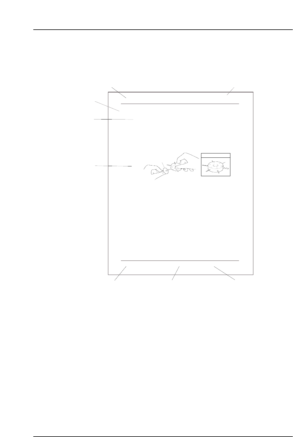
Page Layout
Each page indicates the part number, chapter number and title, section title , manual
name, page number, and the edition number of the manual.
Part number
The part number to which each chapter belongs is shown on the header on each page.
Chapter number and title
The title of each chapter is shown in the header on each page. Each part may contain one
or more chapters.
Section title
Each chapter may be divided into several sections. The section number is composed of
the number of the chapter to which the section belongs, followed by a sequential number
for each section.
1. Cleaning
1.1 Cleaning the Nozzles
Point
Because the nozzles operate by vacuum pressure, sometimes foreign materials are drawn
in. Nozzle blockage occurs when particles of dust, glue, and solder paste are drawn in
and solidify. If this blockage is not corrected, pick-up errors will occur and placing
performance will drop.
Procedure
If a certain nozzle consistently causes pick-up errors, clean it out by inserting and turning
a drill bit as shown in the illustration below.
1.2 Cleaning the Fluorescent Disk (Every Month)
Point
If dust or other fine particles build up on the fluorescent disk, the percentage of UV light
reflection from the station 6 UV lamp will be reduced. If this reflected light is
insufficient, a proper image can not be captured during vision processing. Vision
processing errors thus occur and placing performance drops.
Procedure
If a certain nozzle consistently causes pickup errors, clean its fluorescent disk with a soft
brush (the type of brush used for cleaning a camera lens is best).
Note : Do not rub the fluorescent disk with a rag. Rubbing the fluorescent disk makes grime
adhere to the disk, which causes vision processing problems. If grime cannot be removed,
replace the fluorescent disk.
Nozzle
JIG No. AWPJ8100
CP6M3001Ea
Part 3 Chapter 1 Cleaning
Edition 1.1 3-1-1 CP-6-series Mechanical Reference
Chapter title
Chapter number and title
Manual name
Edition number
Page number
CP6MF003E
Body
Part number
Section title

Body
The information needed to understand the workings of the machine and how to perform
operation is explained using text and illustrations.
Page number
A three digit hyphenated number appears in the footer on each page. The first digit of
each page number indicates the part number, the second digit indicates the chapter
number within the part, and the final digit is the sequential page number within that
chapter. Page 1-2-1, for example, indicates that this is the first page in the second chapter
of part 1.
Manual name
The name of the manual that appears on the cover is also shown in the footer on each
page.
Edition number
The edition number is updated each time the manual is revised, with the number
reflecting the scale of changes that were made.
Minor revision: Minor changes are reflected in the part of the edition number after
the decimal point, for example, a change from edition 1.0 to 1.1. This
change is made on the revised pages only, and these pages can be
downloaded as required from Fuji's website.
Major revision: If major changes are made, the edition number is increased by one,
for example, a change from edition 1.0 to 2.0.
Note: The reference numbers at the bottom right of the illustrations are for administrative
purposes only, and are in no way connected to the content of the manual.
Notation Conventions Used in this Manual
The notation conventions employed in this manual are described below.
[Production] command The names of the command buttons are enclosed in
brackets, and use the verb “press”.
START button Buttons on the machine are written exactly as they
appear, and use the verb “press”.
“Production” command section The names of commands that have been grouped
together are enclosed in quotation marks.
[TAB] key Keys on the keyboard appear in brackets.
About This Manual
Edition 1.6 iii CP-6-series Mechanical Reference