CP-6-series Mechanical Reference.pdf - 第50页
Station 11 : The machine places the part on the board. If the vision processing declares that the part is no good (NG) at station 6, the part is not placed. Station 12 : Fine-theta reverse is performed. The angle of thet…
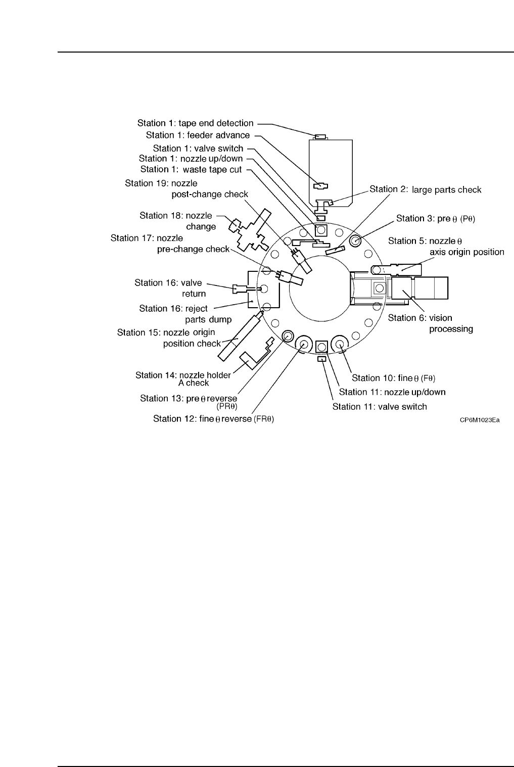
2.1.5The Twenty Stations
Functions of the 20 Stations
The 20 placing head positions are each assigned a station number.
Each of these stations has a special function, as explained below.
Station 1 : The head picks parts from the feeder, advances the feeder tape and
checks for the tape end.
Station 2 : A sensor checks for the pick-up of large parts.
Station 3 : The machine performs pre-theta (Pθ) adjustment. Pre-theta rotates
the part only +90° or -90° depending on the value that is set in the
program. After vision processing is carried out at station 6, fine
theta (Fθ) rotation is carried out at station 10. Because only slight
rotational adjustment is performed in fine-theta, placement speed is
faster and part slippage is minimal.
Station 5 : The placing head is rotated back to the position where it was prior
to St3 Pθ-angle rotation.
Station 6 : Either the wide or the narrow view CCD camera checks whether or
not the part was picked and if the part shape is correct.
Station 10 : Fine theta (Fθ) adjustment is carried out. The results of vision
processing, final adjustments are carried out using servo-motor to
the placing angle.
Part 1 Chapter 2 Functions of Each Component
Edition 1.1 1-2-10 CP-6-series Mechanical Reference

Station 11 : The machine places the part on the board. If the vision processing
declares that the part is no good (NG) at station 6, the part is not
placed.
Station 12 : Fine-theta reverse is performed. The angle of theta rotation that
was performed at station 10 is now performed in reverse.
Station 13 : Pre-theta reverse is performed. The angle of theta rotation that was
performed at station 3 is now performed in reverse.
Station 14 : The nozzle holder's A-position (for production information) is
checked.
Station 15 : Check to verify that the nozzle has returned to its origin position.
Station 16 : Part which failed vision processing at St6 (and was therefore not
placed) is discarded.
Station 17 : Nozzle position pre-change checks are performed for six nozzles.
Station 18 : Nozzle change is performed using a servo motor.
Station 19 : Nozzle position post-change checks are performed for six nozzles.
Part 1 Chapter 2 Functions of Each Component
Edition 1.1 1-2-11 CP-6-series Mechanical Reference
2.2 Parts Supply System
2.2.1Feeders
This feeds the tape on which parts are mounted to the pick-up position at station 1. Only
the CP-6-series feeders can be used on the CP-6-series machines.
2.2.2Device Tables (except for CP-652CE)
Located behind the machine, the device table consists of left and right tables,
servomotors, ball screws and related parts.
The device table is the location where the feeders are mounted. Tape feeders are set up
on the device table in the arrangement specified in the placing program. During
production, the device tables move the feeders directly under station 1 in the order
specified in the program. Station one nozzle then lowers and picks up the part.
The two device tables can be operated as a single unit or two separate units. The
following three modes are available:
Table Mode Selection
• Device change mode : When a parts related error occurs, the other table is
automatically selected.
• Changeover mode : Only one table operates at a time. The other table is
automatically selected at the end of the current program.
• Joint mode : In joint mode, the two tables move as one.
The above table selections are possible. Each device table has its own motor and can
work independently of the other. In the joint mode, the two device tables move in
synchronicity.
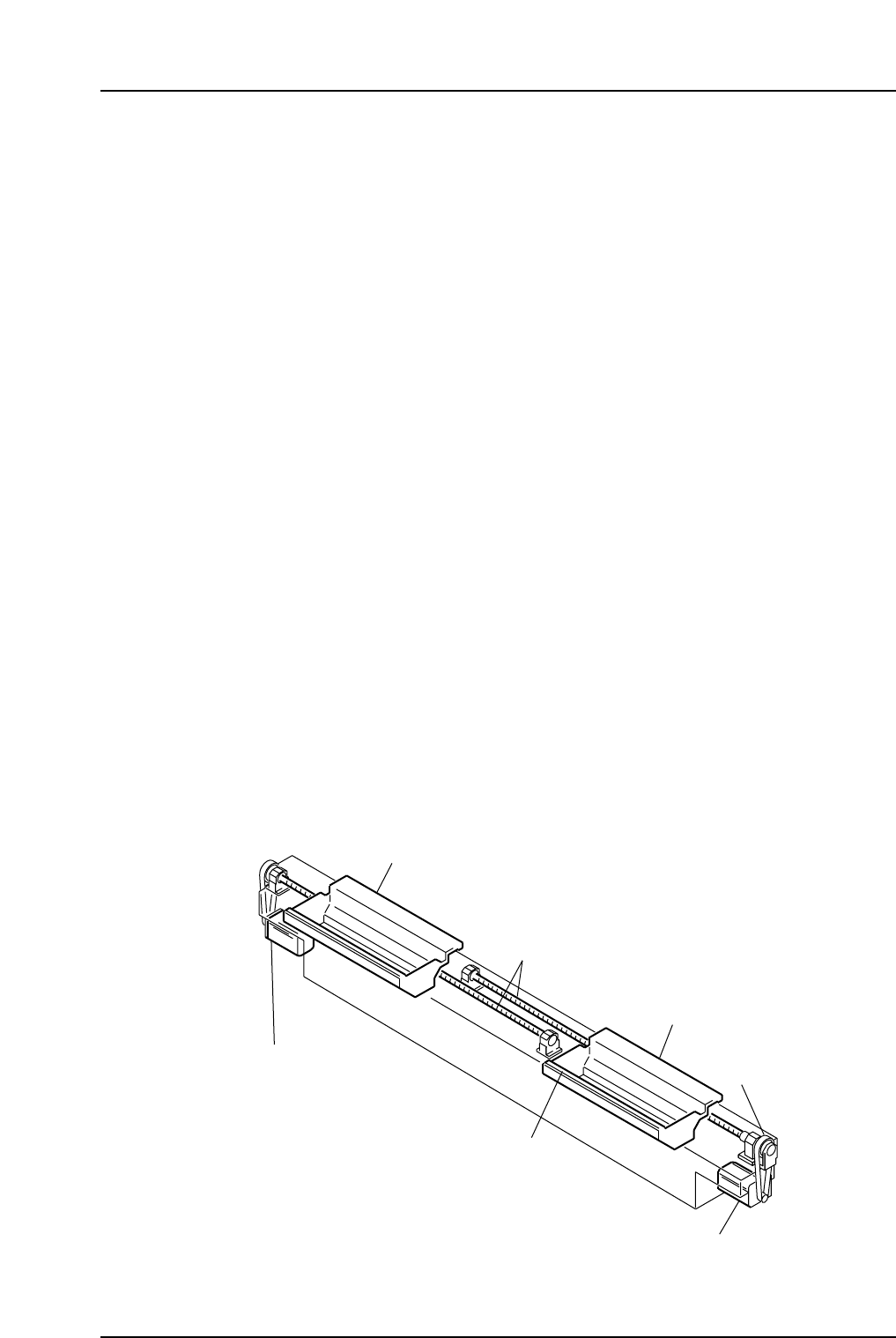
Device Table Configuration
The major components are shown in the following figure.
D1-axis motor
Table 1
Table 2
Timing belt
Tape feeder vibration
reduction assembly
D2-axis motor
Ball screws
CP6M1024E
Part 1 Chapter 2 Functions of Each Component
Edition 1.1 1-2-12 CP-6-series Mechanical Reference