CP-6-series Mechanical Reference.pdf - 第59页
c. Vision Processing Board VM-4800 The next slot in the rack is left open. The next two slots to this contain the vision processing card (VP). The VM-4800 VP card is a double card. The first card of the pair contains the…
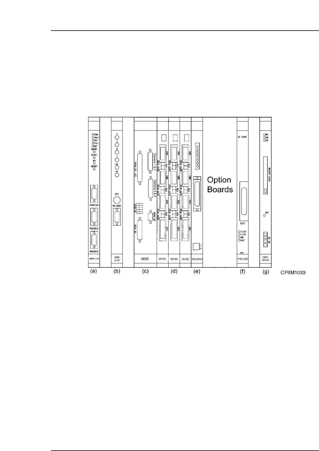
2.6 The VME Rack
This section describes the functions of each of the boards in the VME rack. The VME
boards are installed in the VME rack located in control box 2. The VME rack is the nerve
center of the machine, where all decisions are made, and all processes are conducted.
The rack contains everything from the CPU to the Memory Board.
Excluding optional boards there are 9 boards in the rack, each with its own individual
and important function.
The functions of each board in the rack are detailed below.
a. CPU Board HIMV-134
Starting from the left of the rack, the first card is the CPU. All machine functional
decisions are made here. In addition, programs, part data, and also proper and status
data are stored in the CPU card’s onboard memory. Up to ten individual programs can
be stored in the CPU’s memory at the one time. This card controls all the other cards in
the rack.
b. Console Board AVME-311AF/FH1017A
The second card in the rack is the color video driver board, often commonly referred to
as the console board. This card receives the display data from the CPU card via the
mother board. The primary purpose of this board is to convert binary data from the CPU
board into CRT format to be displayed on the CRT monitor. The connectors on the front
of the card are: R (red), G (green), B (blue), H (horizontal), V (vertical) and I (intensity).
These connectors lead to the front and rear color monitors.
Note: This board does NOT drive the black and white parts display monitor.
Part 1 Chapter 2 Functions of Each Component
Edition 1.1 1-2-19 CP-6-series Mechanical Reference

c. Vision Processing Board VM-4800
The next slot in the rack is left open. The next two slots to this contain the vision
processing card (VP). The VM-4800 VP card is a double card. The first card of the pair
contains the following: custom video processing chips, CPU, RAM, SCSI controller, and
the VME interface. The second card contains: image digitizer, RGB display controller,
serial line controller, and the camera inputs. The two cards communicate via a direct
board to board connector (only the CPU card communications are on the VME bus).
Image data is captured by a SONY or Toshiba CCD camera mounted above the prism
system. The data is then relayed to the VP frame grabber and is analyzed by the CPU
(operating at 25 MHz). Only resultant data is reported to the CP-6’s main CPU (this data
is either X, Y and angular offsets, or an error code). The operational code is loaded from
the SCSI RAM board into the on-board memory of the VP card during machine boot-up.
d. Servo Boards IS70C
The next three cards in the rack are the servo driver cards. These cards interface the CPU
card to the servo amps. The first card controls the C-, FRQ- and Z-axes. The second
controls the X-, Y- and FQ-axes. and the third controls the D1-, D2- and NC-axes.
e. I/O Interface Board MX250RV01
This board interfaces the VME bus (mainly the CPU card) to the Programmable Logic
Controllers (PLC). These are I/O (input/output) handlers. For an output, the decision is
made by the CPU to turn ON/OFF a port (relay, solenoid, LED, etc.). The signal travels
to this card via the bus. The card then routes the signal to the appropriate PLC, either
the main direct I/O PLC or the loader I/O PLC. The actual switching signal is sent by
the PLC, (usually to a relay) which actually drives the device (solenoid, valve, etc.). The
input side works the same way but in an opposite path.
f. SCSI Board FSC-30E/F
The primary job for the Small Computer System Interface (SCSI pronounced “skuhzee”)
RAM board is as a VP firmware interface card. Upon power ON, the VP uses its own
small boot ROM to get booted. At this point, the VP firmware (processing algorithm) is
transferred from a ROM card installed on the SCSI board to the VP board.
In addition, the VP board does not have the ability to save vision data in its RAM after
the machine has been turned off. This data must be saved externally. This is the other
job of this board.
g. MP Board HIMV-924A2
The last card in the rack is one of the most important. The MP board has three main
functions: power failure detection, battery back-up, and memory card interface. When
the machine is first powered up, the CPU boots off the first memory it can find. These
are the boot ROM’s on the CPU board itself (S10 & S6). These chips are not normally
changed when the firmware is upgraded. Once this firmware is used for initial booting,
the CPU will access the MP board. The bulk of the machine control software is stored on
the firmware card inserted into this interface board.
Part 1 Chapter 2 Functions of Each Component
Edition 1.1 1-2-20 CP-6-series Mechanical Reference

The second purpose of the MP board is to watch for a drop in the main AC voltage. The
100V AC secondary side of the main transformer is monitored (the three red wires
leading into the bottom of the card are for this purpose). The MP board is able to detect a
full wave failure within 16.6 ms and begin its next task.
The final job of the MP board is to supply the CPU card with enough voltage to preserve
the contents of the memory. A 3.6 VDC 2,000 MAH Lithium battery is used to do this.
When the battery is drained, the machine will lose its memory (indicated by the message
“Memory back-up NG”) when the power is turned off.
2.7 Pneumatic Control System
This controls the flow and pressure of air (and/or vacuum) from the inlet to where it is
required.
Part 1 Chapter 2 Functions of Each Component
Edition 1.1 1-2-21 CP-6-series Mechanical Reference