CP-6-series Mechanical Reference.pdf - 第84页
4.2 Reference Pin Changeover (When Changing Pin Diameter) Caution: When replacing pins, never loosen the securing bolt on the pin block. If this block is loosened, the X0/Y0 Proper values will change and part placement w…
4. Board Positioning Pins
4.1 Setting the Board Positioning Pins
Procedure
WARNING
Turn off the 200 V servo power before carrying out this work.
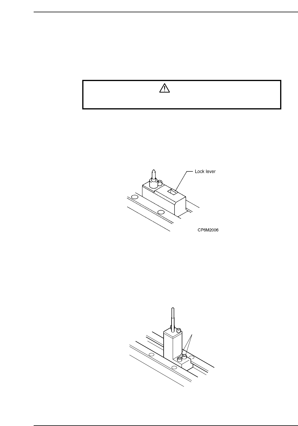
<4000 type>
Push in the lock lever and slide the secondary pin block to adjust the position of the
secondary pin to the hole in the board.
Caution: Do not loosen the bolt that locks the reference pin block in place. When this bolt is
loosened the Proper data will change thereby making it necessary to measure the
Proper data again.
Note: For CP-643E/CP-643ME, refer to Part 9, Chapter 7. “Setting the Board Positioning
Pins”.
<5000 type>
Release the locks bolts and slide the reference pin holder to align the position of the pin
with the hole in the board.
Caution: Loosen the bolt that locks the reference pin block in place. When this bolt is loosened
the Proper data will change thereby making it necessary to measure the Proper data
again.
Bolt
CP6M2007
Part 2 Chapter 4 Board Positioning Pins
Edition 1.0 2-4-1 CP-6-series Mechanical Reference
4.2 Reference Pin Changeover (When Changing Pin
Diameter)
Caution: When replacing pins, never loosen the securing bolt on the pin block. If this block is
loosened, the X0/Y0 Proper values will change and part placement will be misaligned.
Procedure
<4000 type>
1. Press [LOADER] - [LOADING PSTN] and START.
The XY-table moves to the loading position.
2. Press [LIFTER ▲]. The XY-table is raised to the same height as the in/out-
conveyor.
3. Press the EMERGENCY STOP button.
WARNING
Turn off the 200 V servo power before carrying out this work.
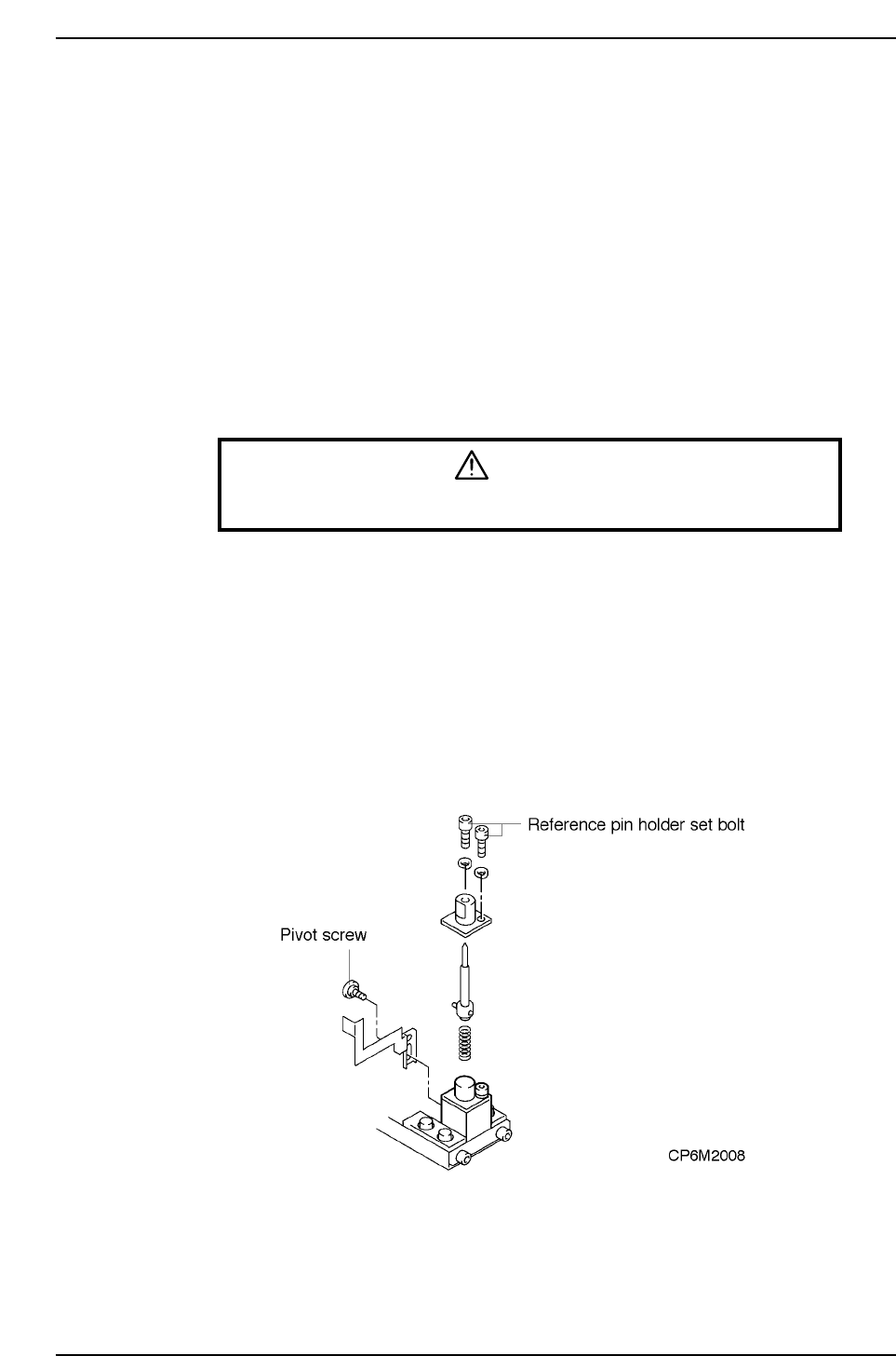
4. Unscrew the pivot screw. (Models other than CP-642, CP-642M, CP-643E, and
CP-643ME)
5. Unscrew the pin holder set bolt.
6. Remove the pin and holder from the block. Be careful that the spring loaded
beneath the pin does not shoot the pin out.
7. Change the pins.
8. After changing the pins, check to see if the spring pin which is attached to the
bottom of the reference pin is inserted in the hole of the dog. Repeat the steps
given thus far in reverse order to reattach the pin.
9. Press [LIFTER ▼]. The XY-table is lowered to the height for placing.
Part 2 Chapter 4 Board Positioning Pins
Edition 1.0 2-4-2 CP-6-series Mechanical Reference
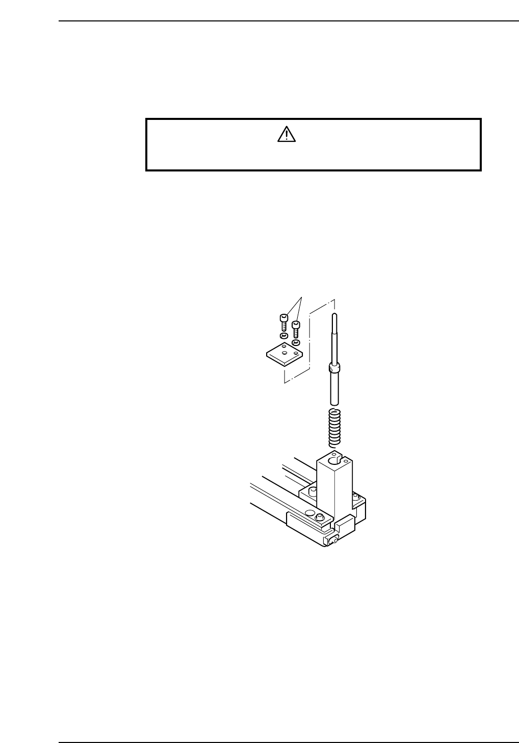
<5000 type>
1. Press [LOADER] - [LOADER PSTN] followed by the START button to move the
XY-table to the loading position.
2. Press [LIFTER ▲] to raise the XY-table to the same height as the in/out-conveyor.
3. Press the EMERGENCY STOP button.
WARNING
Turn off the 200 V servo power before carrying out this work.
4. Unscrew the pin holder bolts.
5. Remove the pin and holder from the block. Be careful that the spring beneath the
pin does not shoot the pin out.
6. Change the pin.
7. After changing the pin, repeat the steps given thus far in reverse order to install
the new pin.
8. Press [LIFTER ▼] to lower the XY-table.
Bolt
CP6M2009
Part 2 Chapter 4 Board Positioning Pins
Edition 1.0 2-4-3 CP-6-series Mechanical Reference