00194563_03_E.pdf - 第10页
1 – 10 Y X Y X Y X X 2 1 Y X Y X Y X Y X + + 1 2 3 4 Y The x-a xis of the comp onent does not nec essarily h a ve to be its long side. This may be the c ase, for example, when the noz zle has to be at 90° to th e compone…

1 – 9
Introduction
0° Description of the components
In order to work with uniformly defined package forms, the description of standard
components is subject to four rules. This is referred to as the “0° description”. It allows the
pickup angle for placement to be defined exactly.
To describe the package form of a component, the dimensions should always be
taken from the corresponding data sheet. It should be noted that it is always the
top view of the component that is described.
The display area of the package form (GF) editor always shows the 0° description of a component.
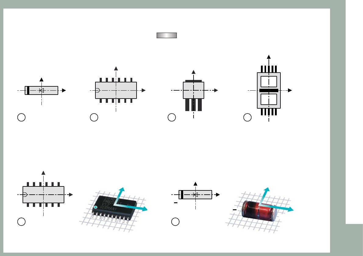
The zero point of the coordinate system is always at the center of the display area in the package
form (GF) editor. The x-axis points to the right, and the y-axis points upward. The component‘s
center point generally corresponds to the zero point of the coordinate system. Rule 1 defines the
alignment of the sides of the component in the x- and y-axis directions.
Rule 1: The long side of a nozzle with a rectangular suction area must be aligned
along the x-axis of the component.
When the component is picked up, the x-axis of the component always points in the same
direction as the long side of the nozzle (exception: special nozzles with 90° rotation).
1 – 10
Y
X
Y
X
Y
X
X
21
Y
X
Y
X
Y
X
Y
X
+
+
1 2 3 4
Y
The x-axis of the component does not necessarily have to be its long side. This may be the case,
for example, when the nozzle has to be at 90° to the component‘s long side because of holes
through the component (see figure: no. f nozzle = ).
Rule 2: Pin 1 is in the lower left corner or in the center of the component‘s left side.
In the case of diodes, the anode (+) must point in the positive x-direction.
1 – 11
Y
X
Y
X
Y
X
Y
X
Introduction
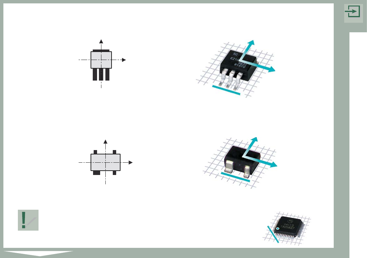
Rule 3: The side with the most pins is at the bottom.
Rule 4: If the component has any unusual features, such as a wider pin,
this feature is at the bottom.
Rule 1 has the highest priority, followed by rules 2, 3 and 4 in that order.
The sample components at the beginning of each chapter are
shown in accordance with the four rules.
The marking on the example (shown beside) indicates the
lower left corner of the component.