00194563_03_E.pdf - 第12页
1 – 12 Right Allocation Nozz le – Component at C& P Pla cement Heads T o avoid rec ognition pro blems at small struc tures the c omponent must be in the foc us range of the c amera. The foc us range of the C&P-20…
1 – 11
Y
X
Y
X
Y
X
Y
X
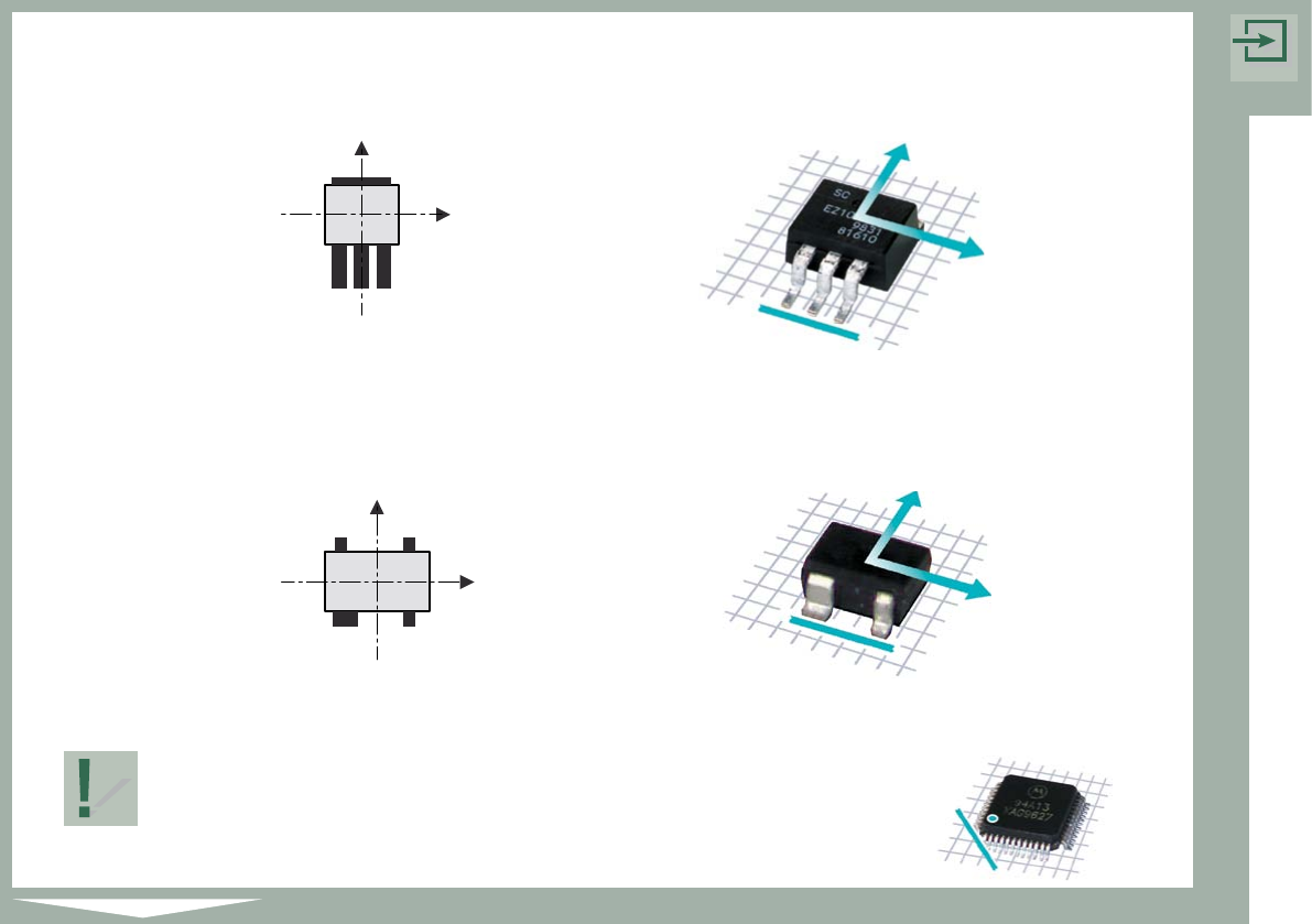
Introduction
Rule 3: The side with the most pins is at the bottom.
Rule 4: If the component has any unusual features, such as a wider pin,
this feature is at the bottom.
Rule 1 has the highest priority, followed by rules 2, 3 and 4 in that order.
The sample components at the beginning of each chapter are
shown in accordance with the four rules.
The marking on the example (shown beside) indicates the
lower left corner of the component.
1 – 12
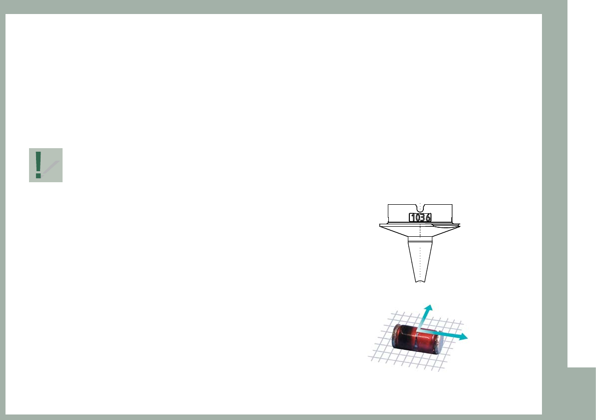
Right Allocation Nozzle – Component at C&P Placement Heads
To avoid recognition problems at small structures the component
must be in the focus range of the camera.
The focus range of the C&P-20 camera is between 9.4 und 11.4 mm (10.4 +/– 1 mm).
The focus range of the C&P-6 / C&P-12 camera is between 13.0 und 17.0 mm (15 +/– 2 mm).
Selecting the right nozzle for a component
it has to be checked if the sum of nozzle length
and component height is inside this interval.
Example:
Nozzle length L = 9.4 mm
Component height H = 1.2 mm
Sum = 10.6 mm
1 – 13
Introduction
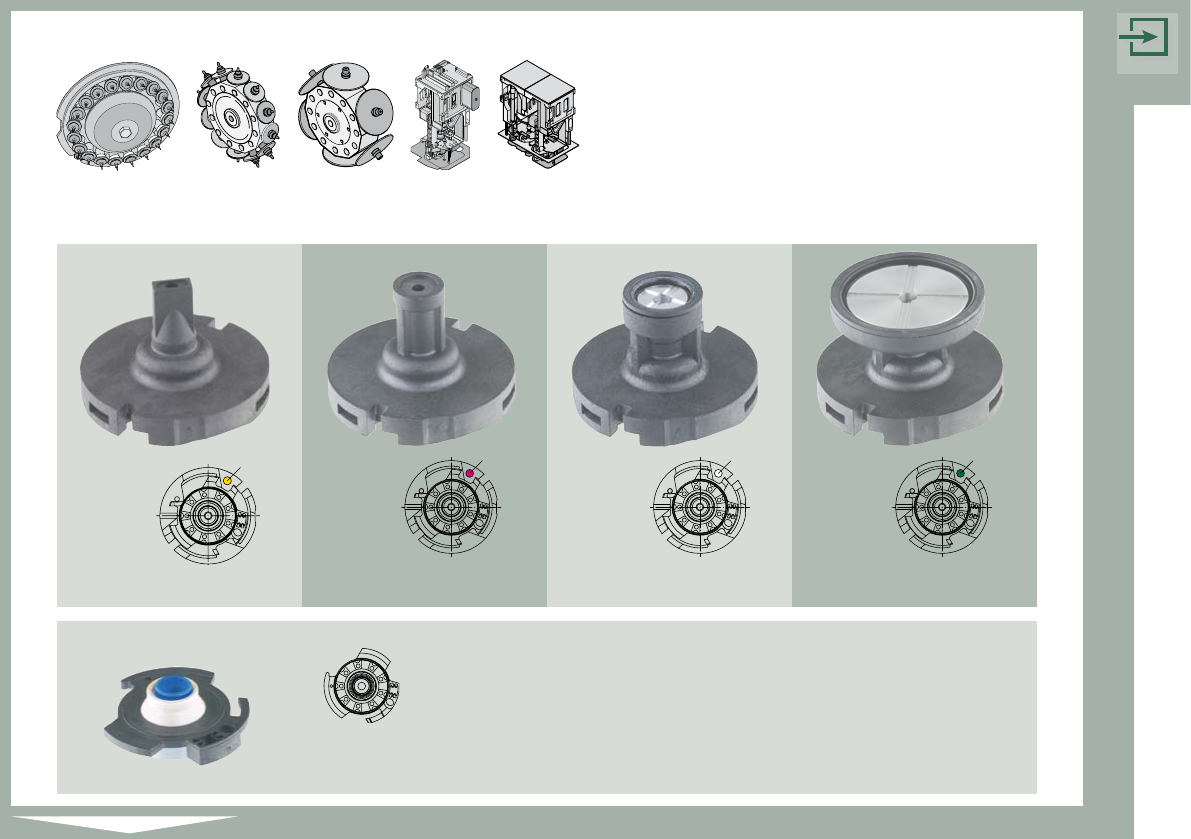
Overview of
Standard Nozzles
Standard Nozzles of the 5xx Nozzle Series
516
L = 20 mm
Item-No. 03012036-01
519
L = 18.7 mm
Item-No. 03012034-01
517
L = 20 mm
Item-No. 03012042-01
518
L = 18.7 mm
Item-No. 03012011-01
Nozzle adapter sealing for TWIN
Item-No. 03011583- 02
Color marking
Color marking Color marking Color marking