IPC-SM-782A-表面贴装焊盘图形设计标准.pdf.pdf - 第198页
This Page Intentionally Left Blank IPC-SM-782A Subject Plastic Ball Grid Array Date 4/99 Section 14.1 Revision — P a g e2o f2
1.0 INTRODUCTION
This section covers land pattern recommendations for ball
grid array (BGA) contact devices. Each subsection contains
information in accordance with the following format.
1.0 Scope
2.0 Applicable Documents
3.0 General Component Description
4.0 Component Outline
5.0 Land Pattern Dimensions
6.0 Land Pattern Analysis
The following is the table of contents for this section:
Table of Contents
Components with Ball Grid Array Contacts
Section
14.1.1
14.1.2
14.1.3
Standard Source
JEDEC MO-151
JEDEC MO-151
JEDEC MO-151
Pitch
1.5 mm
1.27 mm
1.0 mm
2.0 APPLICABLE DOCUMENTS
The following documents, of the issue in effect on the current
revision date of this section, form a part of this specification to
the extent specified herein.
2.1 Joint Electronic Device Engineering Council
1
JEDEC Publication 95 Registered and Standard Outlines for
Solid State and Related Products:
• Plastic Ball Grid Array (PBGA), MO-151
3.0 GENERAL INFORMATION
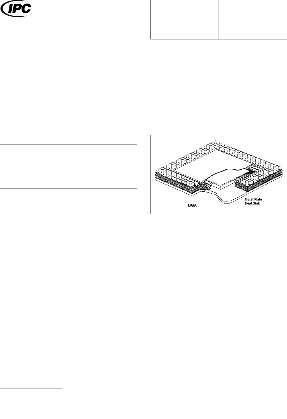
3.1 Component Description
The Grid Array device family
includes square and rectangular package configurations and
is furnished in a plastic base material. Figure 3-1 shows the
elements of a BGA. Base material serves as a mounting struc-
ture for attaching the die. Depending on the physical charac-
teristics of the material, flip-chip or wire bond technologies
may be employed to route the signal from the die bond pads
to the array matrix on the base interface structure.
1. JEDEC: 2500 Wilson Blvd., Arlington, VA, 22201-3834, USA.
IPC-782143-1
Figure 3-1 Ball Grid Array IC package example
IPC-SM-782
Surface Mount Design
and Land Pattern Standard
Date
4/99
Section
14.1
Revision
—
Subject
Plastic Ball Grid Array
Page1of2

This Page Intentionally Left Blank
IPC-SM-782A
Subject
Plastic Ball Grid Array
Date
4/99
Section
14.1
Revision
—
Page2of2

1.0 SCOPE
This subsection provides the component and land pattern
dimensions for square 1.5 mm pitch Plastic Ball Grid Arrays
(PBGA).
2.0 APPLICABLE DOCUMENTS
See Section 14.0 for documents applicable to the subsection.
3.0 COMPONENT DESCRIPTION
These components are all on 1.5 mm pitch. They are available
in a wide variety of body sizes. The data supplied in the detail
and table reflect a full matrix. Specific contact and depopula-
tion and pin assignment must be furnished by the device
manufacturer (see Section 14.0 for more information on
depopulation methods).
IPC-SM-782
Surface Mount Design
and Land Pattern Standard
Date
4/99
Section
14.1.1
Revision
—
Subject
1.5 mm Pitch PBGA
JEDEC MO-151
Page1of6