IPC-SM-782A-表面贴装焊盘图形设计标准.pdf.pdf - 第200页
4.0 COMPONENT DIMENSIONS Figures 1a-1b provides the component dimensions for square PBGAs. Component Contact Array ABCD W PH F o r G Identifier Rows x Cols. max max max max nom. basic max nom. PBGA 7x7 FE16 4x4 7.00 7.00 …

1.0 SCOPE
This subsection provides the component and land pattern
dimensions for square 1.5 mm pitch Plastic Ball Grid Arrays
(PBGA).
2.0 APPLICABLE DOCUMENTS
See Section 14.0 for documents applicable to the subsection.
3.0 COMPONENT DESCRIPTION
These components are all on 1.5 mm pitch. They are available
in a wide variety of body sizes. The data supplied in the detail
and table reflect a full matrix. Specific contact and depopula-
tion and pin assignment must be furnished by the device
manufacturer (see Section 14.0 for more information on
depopulation methods).
IPC-SM-782
Surface Mount Design
and Land Pattern Standard
Date
4/99
Section
14.1.1
Revision
—
Subject
1.5 mm Pitch PBGA
JEDEC MO-151
Page1of6
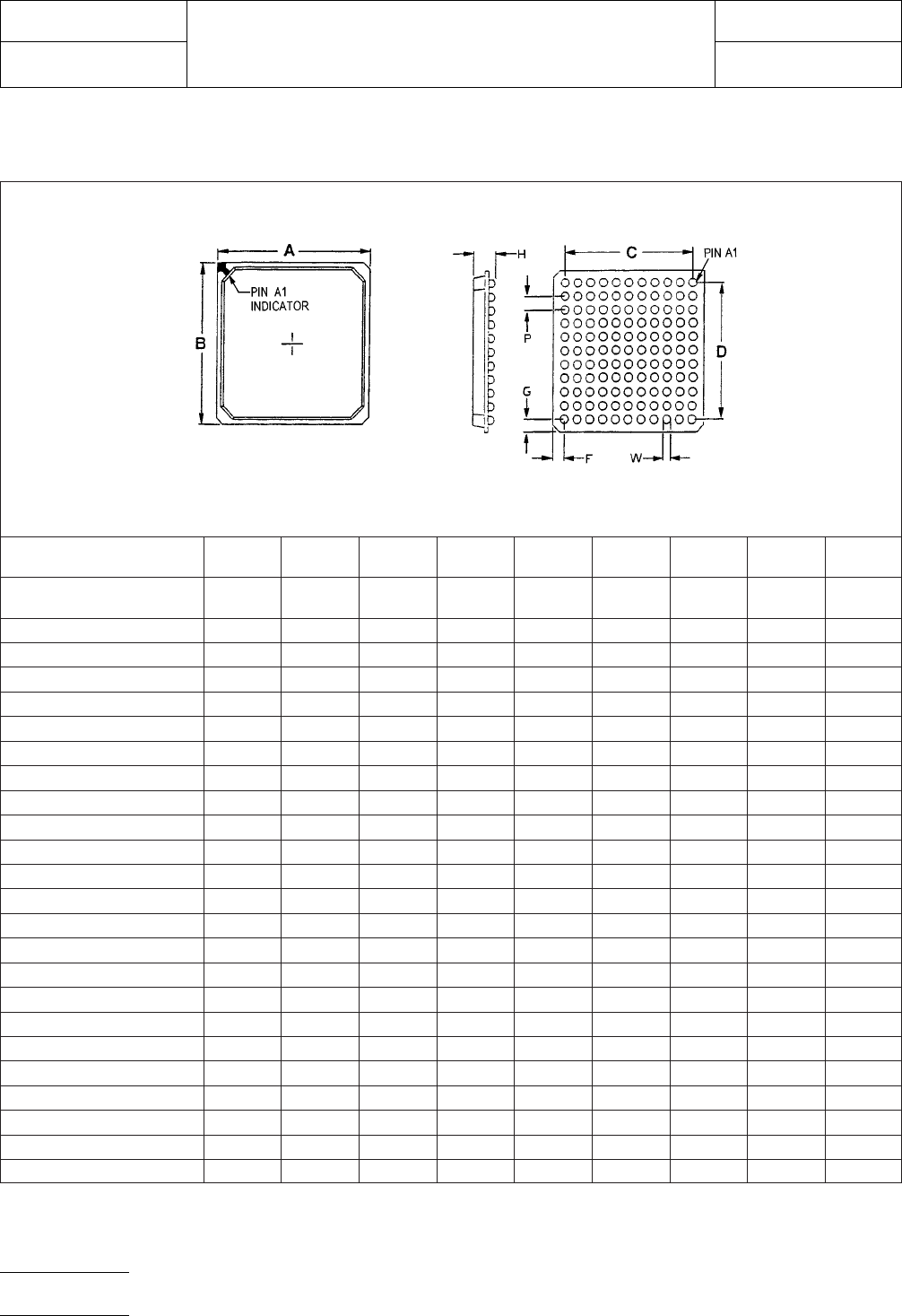
4.0 COMPONENT DIMENSIONS
Figures 1a-1b provides the component dimensions for square PBGAs.
Component
Contact
Array ABCDWPHForG
Identifier
Rows x
Cols. max max max max nom. basic max nom.
PBGA 7x7 FE16 4x4 7.00 7.00 4.50 4.50 0.75 1.50 3.50 1.25
PBGA 7x7 FO9 3x3 7.00 7.00 3.00 3.00 0.75 1.50 3.50 2.00
PBGA 8x8 FO25 5x5 8.00 8.00 6.00 6.00 0.75 1.50 3.50 1.00
PBGA 8x8 FE16 4x4 8.00 8.00 4.50 4.50 0.75 1.50 3.50 1.75
PBGA 9x9 FE36 6x6 9.00 9.00 7.50 7.50 0.75 1.50 3.50 0.75
PBGA 9x9 FO25 5x5 9.00 9.00 6.00 6.00 0.75 1.50 3.50 1.50
PBGA 10x10 FE36 6x6 10.00 10.00 7.50 7.50 0.75 1.50 3.50 1.25
PBGA 10x10 FO25 5x5 10.00 10.00 6.00 6.00 0.75 1.50 3.50 2.00
PBGA 11x11 FO49 7x7 11.00 11.00 9.00 9.00 0.75 1.50 3.50 1.00
PBGA 11x11 FE36 6x6 11.00 11.00 7.50 7.50 0.75 1.50 3.50 1.75
PBGA 12x12 FE64 8x8 12.00 12.00 10.50 10.50 0.75 1.50 3.50 0.75
PBGA 12x12 FO49 7x7 12.00 12.00 9.00 9.00 0.75 1.50 3.50 1.50
PBGA 13x13 FE64 8x8 13.00 13.00 10.50 10.50 0.75 1.50 3.50 1.25
PBGA 13x13 FO49 7x7 13.00 13.00 9.00 9.00 0.75 1.50 3.50 2.00
PBGA 14x14 FO81 9x9 14.00 14.00 12.00 12.00 0.75 1.50 3.50 1.00
PBGA 14x14 FE64 8x8 14.00 14.00 10.50 10.50 0.75 1.50 3.50 1.75
PBGA 15x15 FE100 10x10 15.00 15.00 13.50 13.50 0.75 1.50 3.50 0.75
PBGA 15x15 FO81 9x9 15.00 15.00 12.00 12.00 0.75 1.50 3.50 1.50
PBGA 17x17 FO121 11x11 17.00 17.00 15.00 15.00 0.75 1.50 3.50 1.00
PBGA 17x17 FE100 10x10 17.00 17.00 13.50 13.50 0.75 1.50 3.50 1.75
PBGA 19X19 FE144 12x12 19.00 19.00 16.50 16.50 0.75 1.50 3.50 1.25
PBGA 19X19 FO121 11x11 19.00 19.00 15.00 15.00 0.75 1.50 3.50 2.00
PBGA 21X21 FE196 14x14 21.00 21.00 19.50 19.50 0.75 1.50 3.50 0.75 0
FE = Full Even Matrix
FO = Full Odd Matrix
Figure 1a PBGA component dimension
IPC-SM-782
Subject
1.5 mm Pitch PBGA JEDEC MO-151
Date
4/99
Section
14.1.1
Revision
—
Page2of6
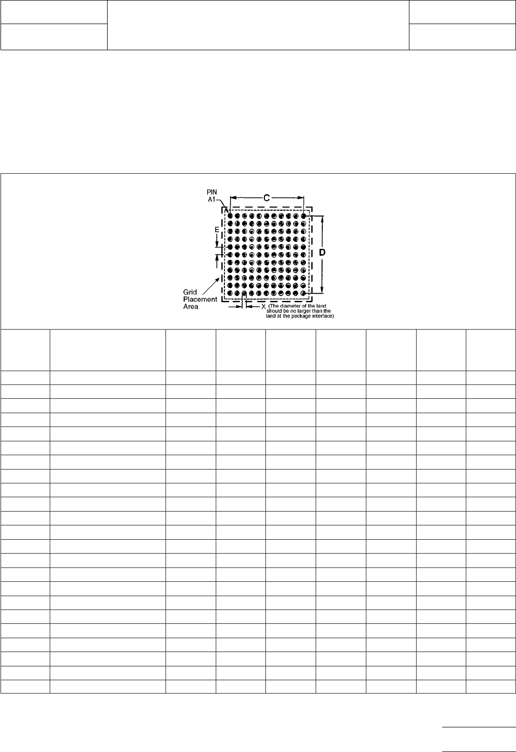
5.0 LAND PATTERN DIMENSIONS
Figures 2a-2b provide the land pattern dimensions for square
PBGA components. These numbers represent industry con-
sensus on the best dimensions based on empirical knowledge
of fabricated land patterns.
Note: The data supplied in the detail and table reflect a full
matrix. Specific contact and depopulation and pin assignment
must be furnished by the device manufacturer.
The dotted line in Figures 2a-2b shows the grid placement
courtyard which is the area required to place land patterns
and their respective components in adjacent proximity without
interference or shorting. Numbers in the table represent the
number of grid elements (each element is 0.5 by 0.5 mm) in
accordance with the international grid detailed in IEC publica-
tion 97.
RLP Component Identifier
Contact
Array
Rows x
Cols.
Max.
Contact
Count C D X E
Placement
Grid
1020 PBGA 7x7 FE16 4x4 16 4.50 4.50 0.60 1.50 16X16
1021 PBGA 7x7 FO9 3x3 9 3.00 3.00 0.60 1.50 16X16
1022 PBGA 8x8 FO25 5x5 25 6.00 6.00 0.60 1.50 18X18
1023 PBGA 8x8 FE16 4x4 16 4.50 4.50 0.60 1.50 18X18
1024 PBGA 9x9 FE36 6x6 36 7.50 7.50 0.60 1.50 20X20
1025 PBGA 9x9 FO25 5x5 25 6.00 6.00 0.60 1.50 20X20
1026 PBGA 10x10 FE36 6x6 36 7.50 7.50 0.60 1.50 22X22
1027 PBGA 10x10 FO25 5x5 25 6.00 6.00 0.60 1.50 22X22
1028 PBGA 11x11 FO49 7x7 49 9.00 9.00 0.60 1.50 24X24
1029 PBGA 11x11 FE36 6x6 36 7.50 7.50 0.60 1.50 24X24
1030 PBGA 12x12 FE64 8x8 64 10.50 10.50 0.60 1.50 26X26
1031 PBGA 12x12 FO49 7x7 49 9.00 9.00 0.60 1.50 26X26
1032 PBGA 13x13 FE64 8x8 64 10.50 10.50 0.60 1.50 28X28
1033 PBGA 13x13 FO49 7x7 49 9.00 9.00 0.60 1.50 28X28
1034 PBGA 14x14 FO81 9x9 81 12.00 12.00 0.60 1.50 30X30
1035 PBGA 14x14 FE64 8x8 64 10.50 10.50 0.60 1.50 30X30
1036 PBGA 15x15 FE100 10x10 100 13.50 13.50 0.60 1.50 32X32
1037 PBGA 15x15 FO81 9x9 81 12.00 12.00 0.60 1.50 32X32
1038 PBGA 17x17 FO121 11x11 121 15.00 15.00 0.60 1.50 36X36
1039 PBGA 17x17 FE100 10x10 100 13.50 13.50 0.60 1.50 36X36
1040 PBGA 19X19 FE144 12x12 144 16.50 16.50 0.60 1.50 40X40
1041 PBGA 19X19 FO121 11x11 121 15.00 15.00 0.60 1.50 40X40
1042 PBGA 21X21 FE196 14x14 196 19.50 19.50 0.60 1.50 44X44
FE = Full Even Matrix
FO = Full Odd Matrix
For land pattern tolerance analysis,
see Section 14.0, Subsection 6.
Figure 2a PBGA land pattern dimensions
IPC-SM-782
Subject
1.5 mm Pitch PBGA JEDEC MO-151
Date
4/99
Section
14.1.1
Revision
—
Page3of6