IPC-SM-782A-表面贴装焊盘图形设计标准.pdf.pdf - 第223页
• Zone 6 Zone 6 is the most important part of the analysis. It is in this area where the user has the opportunity to fine tune the land pattern through the adjustment factor to enhance the pattern for both solder joint fo…
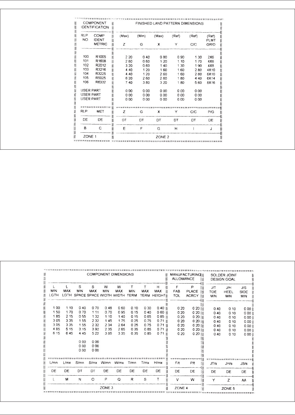
• Zone 3
Zone 3 is where the information must be entered for
describing the relationship of the component dimensions
to be used in the analysis. See Figure A-2.
• Zone 4
Zone 4 represents the manufacturing allowance. This
allowance is for the board manufacturing tolerance, and
for placement accuracy, and is contained in columns V
and W of the spreadsheet for chip resistors. See Figure
A-2.
• Zone 5
Zone 5 represents the solder joint design goal informa-
tion. This information is entered by the user, and reflects
the desired solder joint at the toe, heel and side.
The recommendations come from empirical information
that has been determined over the years for the derivation
of process proven land patterns. See Figure A-2.
Figure A-1 Zones 1 and 2
Figure A-2 Zones 3, 4, and 5
IPC-SM-782A December 1999
A-2
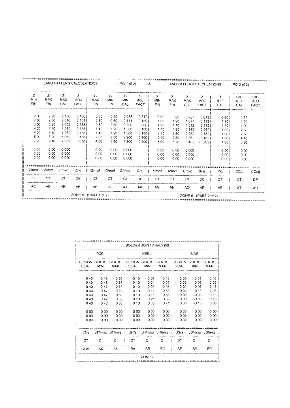
• Zone 6
Zone 6 is the most important part of the analysis. It is in
this area where the user has the opportunity to fine tune
the land pattern through the adjustment factor to enhance
the pattern for both solder joint formation and character-
istics that can be used by the CAD systems. See Figure
A-3.
• Zone 7
Zone 7 provides information as to what has been accom-
plished for the toe, heel, and side fillets. This zone is
divided into three segments. See Figure A-4.
Figure A-3 Zone 6
Figure A-4 Zone 7
December 1999 IPC-SM-782A
A-3
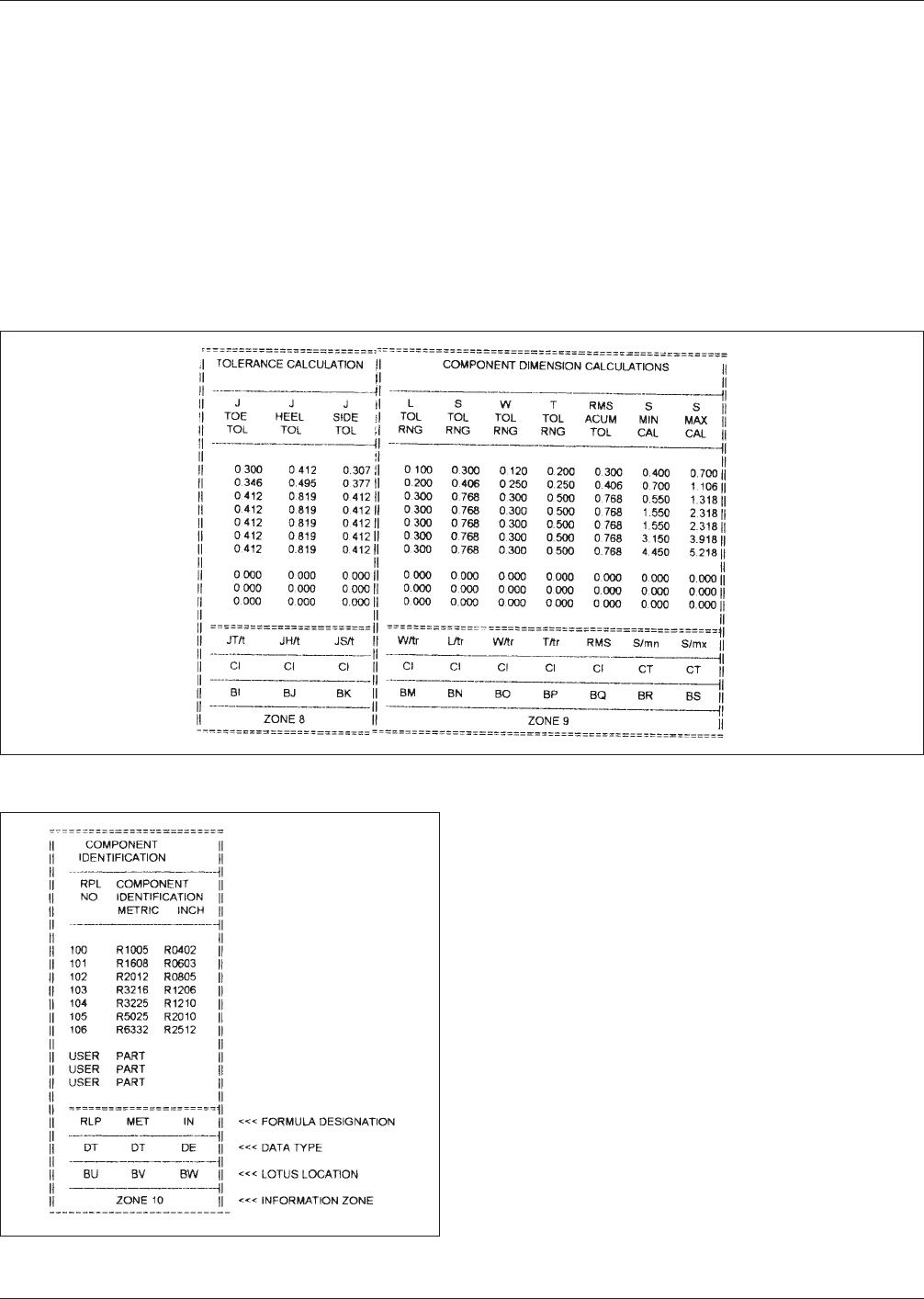
• Zone 8
Zone 8 is the tolerance calculation for toe, heel and side
tolerance, and is kept to the side of the spreadsheet
because this is where the calculations are accomplished.
See Figure A-5.
• Zone 9
Zone 9 is where all the component dimension calculations
are derived. These are mostly calculated information,
although columns BR and BS provide calculated informa-
tion that is transferred to another zone. See Figure A-5.
• Zone 10
Zone 10 again provides information on the component
identification. See Figure A-6.
Figure A-5 Zones 8 and 9
Figure A-6 Zone 10
IPC-SM-782A December 1999
A-4