IPC-SM-782A-表面贴装焊盘图形设计标准.pdf.pdf - 第52页
IPC-782-4-12 Figure 4–12 Thermal cycle excursion rate + 125° + 100° - 65° 400 Cycles 1000 Cycles 0°C 0°C 30 Minutes 30 Minutes 30 Minutes 30 Minutes 30 Minutes IPC-SM-782A December 1999 44
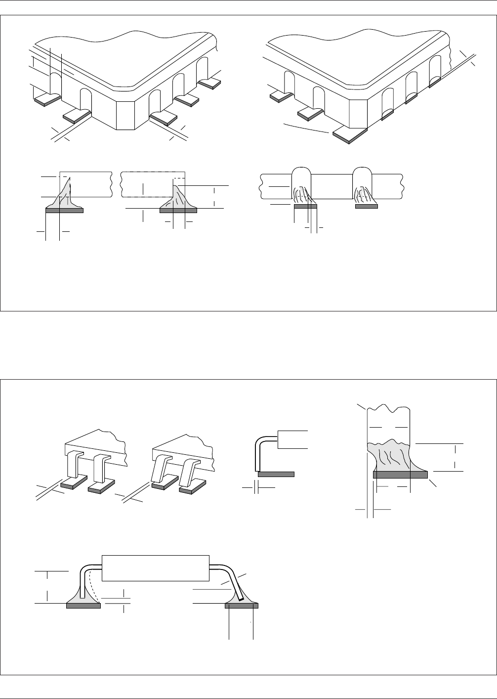
IPC-782-4-10
Figure 4–10 Leadless chip carriers with castellated terminations—joint description
W = Castellation Width
H = Castellation Height
P = Land Length External
to Package
Side OverhangSide Overhang
H
▼
▼
▼
A
▼
▼
▼
A
End Joint Width
B
▼
▼
Side Joint Length
G
▼
D
▼
F
▼
▼
▼
▼
F
C
▼
▼
▼
▼
A
▼
▼
H
P
▼
Corner
metallization
(termination)
fillet required if
land is present
▼
W
▼
▼
▼
▼
▼
IPC-782-4-11
Figure 4–11 Butt joint description
W = Lead Width
T = Lead Thickness
Side Overhang
C
A
▼
▼
F
▼
▼
End Joint Width
▼
Toe Overhang
Is Not
Acceptable
W
▼
▼
▼
A
▼
▼
A
▼
▼
B
Side Joint Length
E
▼
▼
T
▼
▼
F
▼
▼
▼
▼
D
Land
▼
Lead
▼
G
▼
▼
▼
▼
See Note 1, Table 9–9.
Note: See ANSI/J-STD-001 for specific details on minimum acceptability requirements.
December 1999 IPC-SM-782A
43
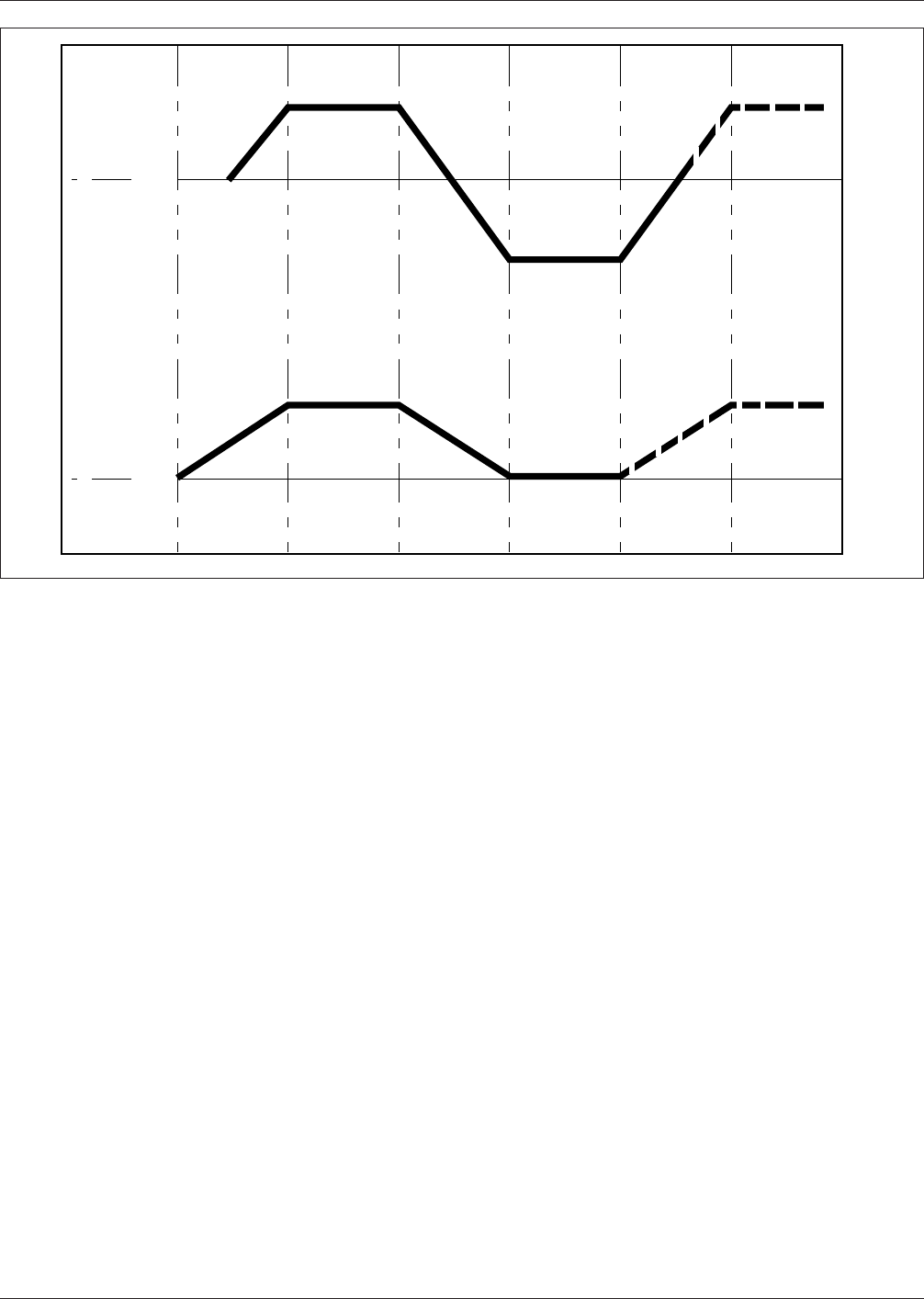
IPC-782-4-12
Figure 4–12 Thermal cycle excursion rate
+ 125°
+ 100°
- 65°
400
Cycles
1000
Cycles
0°C
0°C
30
Minutes
30
Minutes
30
Minutes
30
Minutes
30
Minutes
IPC-SM-782A December 1999
44

5.0 TESTABILITY
5.1 Testing Considerations
5.1.1 Bare Board Test
In testing printed board using
through hole technology, the defect rate and the test meth-
ods chosen are the principle determiners of overall test
cost. Real estate considerations (specifically the percentage
of nodes that are available for bed-of-nails probing) are not
a concern, since 100% nodal access practically comes ‘‘for
free’’. In testing surface mount boards, however, real estate
considerations (in addition to defect rates) impact test
costs, since nodal access determines which test methods
are possible and effective.
5.1.2 Loaded Board Test Given the same test costs,
defect rate can be traded off against real estate. For
example, if the defect rate is relatively high, most boards
will require diagnosis, and the economics of Automatic
Test Equipment (ATE) will demand that full nodal access
be provided for in the board layout. If the defect rate is
low, more time can be spent diagnosing each defect manu-
ally, rather than with ATE, and thus reduce the real estate
impact to less than 100% nodal access. Extremely low
defect levels would theoretically allow 0% nodal access
(no bed of nails test at all), applying only a simple pass/no-
pass test through the edge connector, and throw away fail-
ing assemblies rather than diagnose them.
The major considerations in determining nodal access are:
• Defect rate
• Diagnostic capability
• Real estate impact
—Board area
—Layer count
• Cost impact
Determining the percentage of nodal access to design into
a board layout requires trading off all the issues discussed
previously: defect rate, test development cost, test opera-
tion costs including manual troubleshooting costs, and of
course, impacts on real estate. Short of having no defects
at all, full nodal access remains the most desirable option.
As with Through Hole Technology boards, once the board
is designed (nodal access fixed) and its tests are designed
(test methods fixed), the defect rate becomes the primary
key to reducing test costs. Therefore, defect reporting,
analysis, and correction/prevention are imperative. This
may involve closer supplier relationships to reduce compo-
nent and board level problems, and in-house action to
reduce process-induced problems.
5.2 Nodal Access In the early stages of product develop-
ment cycles, test philosophies and strategies are often
undefined. This is especially true when a company is mov-
ing from one level of packaging technology to the next
higher level of packaging technology, for example, from
through-hole technology to surface mount technology. Dur-
ing these transition periods, the concurrent engineering
approach is essential for designing nodal access for test-
ability into the product. Concurrent engineering is the prin-
ciple vehicle by which test priorities can and should be
moved up to the beginning of the design cycle and
addressed with a higher priority. In the early stages of a
design, a test philosophy should be clearly defined, then a
strategy for executing the tests can be implemented. An
ideal philosophy to adopt is one that identifies all of the
different test types and the level of test that each type
requires.
There are 2 basic categories of PB tests: The bare board
test, and the loaded board test. The bare board test is per-
formed at the end of the fabrication cycle and checks for
shorts, opens, and net list connectivity. The loaded board
tests occur at the end of the assembly cycle and are consid-
erably more complex. They include: Manufacturing
Defects Analyzer (MDA), in-circuit, functional and combi-
national tests.
The test philosophy should be written to encompass what-
ever combination of tests are necessary for the product.
Then, a simple strategy for implementing the required tests
can be defined prior to beginning the design process. Plan-
ning testability at the beginning of a product development
cycle instead of the end can result in significantly lower
test costs per node and provide higher nodal accessibility
throughout the entire process from initial design to final
test.
5.2.1 Five Types of Testing There are five basic types of
tests which can be performed on SMT boards. These are:
• Bare Board Test
Check the unpopulated board for shorts and opens
• Manufacturing Defects Analysis
Checks the populated board for soldering shorts
• In-Circuit Test
Operational verification of each individual component
• Functional Test
Operational verification of functional block of circuits
• Combinational Test
Limited integration of in-circuit and functional test
The first test type is a bare board test which is performed
by the board fabricator. The remaining four test types are
loaded on assembled board tests which are performed after
assembly. The bare board test should be mandatory, while
the loaded board may be tested using any combination of
the four loaded board tests.
5.2.2 Test Philosophy The best test philosophy to adopt
is one that will make provision for executing every test
type available. Even if the product testing procedure is well
defined at the beginning of the development cycle, it may
December 1999 IPC-SM-782A
45