XPM2-Site_Preparation - 第10页
Site Preparation & Installation Section: 2 Page: 10 Revision Date: April 2005 SITE PREPARATION CHECKLIST Prior to Vitronics Soltec installing / commissioning the so lde r reflow system (oven), the oven must be placed…
Site Preparation & Installation Section: 1 Page: 9 Revision Date: April 2005
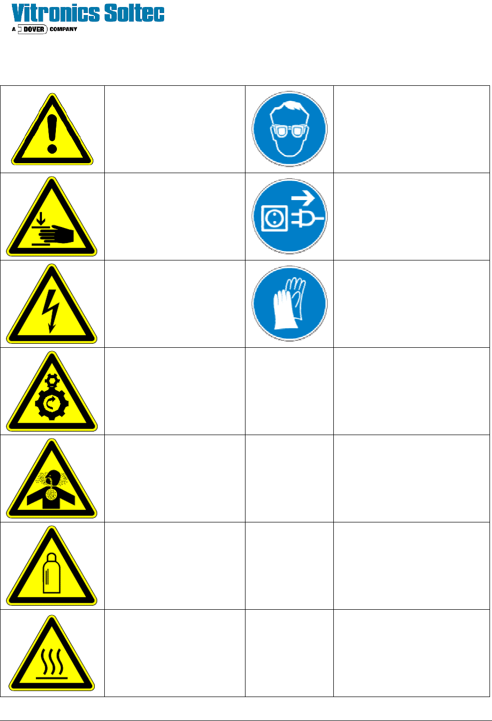
8. DESCRIPTION OF SYMBOLS USED
General Hazard
EYE PROTECTION: When
operation or servicing the on the
machine, always protect your
eyes with safety glasses.
Pinch Point: Moving parts
of the machine may cause
crushing injury
DEERGIZE: Disconnect power
when performing this operation.
HIGH VOLTAGES: High
voltages are present on
various parts of the system.
HAND PROTECTION: When
performing this operation or
service the on the machine,
protect your hands with gloves.
MECHANICAL HAZARDS:
Moving parts may be rotating
or oscillating causing a
hazard.
INHALATION HAZARD:
Vapors or dust may be
emitted which is hazardous
to breath.
GAS CYLINDER:
Compressed gas system is
used, follow all precautions
listed in the MSDS for the
gas being used.
HOT SURFACES: There is
a risk of being burned if you
come in contact with hot
surfaces
Site Preparation & Installation Section: 2 Page: 10 Revision Date: April 2005
SITE PREPARATION CHECKLIST
Prior to Vitronics Soltec installing / commissioning the solder reflow system (oven), the oven must be placed in
line, pre-leveled, and connected to the required facilities by the customer. The checklist below should be
reviewed and completed prior to requesting a site visit by a Vitronics Soltec Service Engineer. Reference the
XPM
2
Installation Drawing and additional requirements herein for details.
___ Exhaust system correctly sized and located?
___ * Electrical power and main circuit breaker switch properly rated, installed and provided to the oven?
___ * Nitrogen source correctly sized, located and plumbed to the oven?
___ Compressed air supply correctly sized, located and plumbed to the oven?
___ * External coolant supply available with proper hose lines and connections?
___ Oven placed in position and pre-leveled?
* Configuration dependent, consult purchase order and equipment specifications for details.
Site Preparation & Installation Section: 2 Page: 11 Revision Date: April 2005
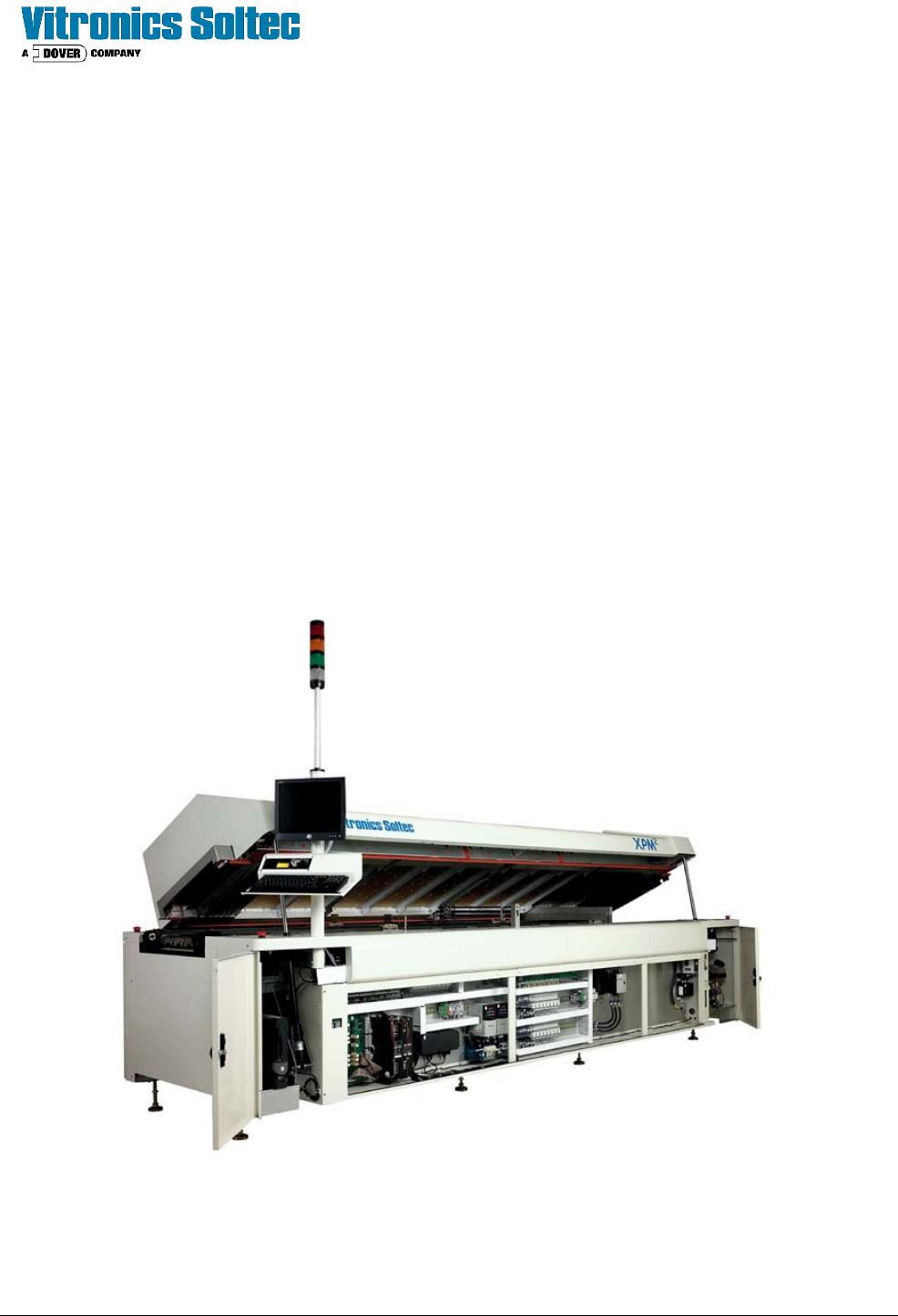
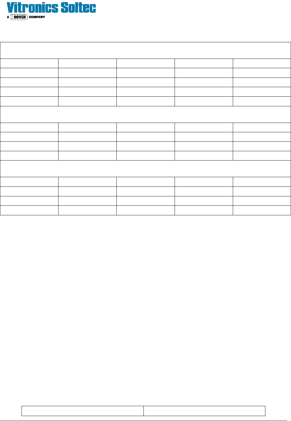
ROOM PLANNING
XPM
2
MODEL
520 730 / 820 940 / 1030 1240
LENGTH (in/cm) 139 / 353 175 / 445 211 / 536 247 / 630
WIDTH (in/cm) 52 / 132 52 / 132 52 / 132 52 / 132
HEIGHT (in/cm) 57 / 144 57 / 144 57 / 144 57 / 144
WEIGHT (lb/kg) 2800 / 1275 3950 / 1800 5000 / 2275 6100 / 2770
Oven And Skid
LENGTH (in/cm) 172 / 379 208 / 528 244 / 538 280 / 617
WIDTH (in/cm) 67 / 171 67 / 171 67 / 171 67 / 171
HEIGHT (in/cm) 65 / 165 65 / 165 65 / 165 65 / 165
WEIGHT (lb/kg) 3000 / 1360 4200 / 1905 5225 / 2375 6360 / 2885
Oven And Crate
LENGTH (in/cm) 177 / 450 213 / 541 249 / 633 285 / 724
WIDTH (in/cm) 67 / 171 67 / 171 67 / 171 67 / 171
HEIGHT (in/cm) 76 / 193 76 / 193 76 / 193 76 / 193
WEIGHT (lb/kg) 3425 / 1555 4850 / 2200 5950 / 2700 6885 / 3125
Oven Clearances
A full 36” clearance space should be provided around front and rear of the oven to allow for a
safe working area. All applicable Codes and Regulations should be considered when
providing service space. Oven Height listed is with the “Hood down” and does not include
ductwork.
Access
Doors and other openings should be large enough to accommodate the personnel and equipment involved in
moving and placing the oven. Allow approximately 6" (15 CM) of clearance above the oven for lifting.
Floor
The oven must be located on a level, dust free concrete floor not subject to vibration from other equipment or
passing fork trucks. Vibration in the floor may cause problems with the oven 's conveyors and the printed
circuit boards being processed.
Air Conditioning
Air Conditioning Load for all oven Models is not more than 35,000 BTU/ hour.
The system is designed to operate within the following environmental conditions:
Temperature: 55 to 90
o
F (13
to 32
o
C) Humidity: 20 to 90% Non Condensing