XPM2-Site_Preparation - 第13页
Site Preparation & Installation Section: 2 Page: 13 Revision Date: April 2005 FACILITY SERVICES & CONNECTIONS Exhaust Specifications Number of Connections per Oven 2 Oven Exhaust Duct Size 8” Facility Duct Materi…
Site Preparation & Installation Section: 2 Page: 12 Revision Date: April 2005
Site Preparation & Installation Section: 2 Page: 13 Revision Date: April 2005
FACILITY SERVICES & CONNECTIONS
Exhaust Specifications
Number of Connections per Oven 2
Oven Exhaust Duct Size 8”
Facility Duct Material High Temperature Flexible Hose – Rated For 125
0
C Minimum
Onload Stack ( Entrance ) Offload Stack ( Exit )
CFM IWC CFM IWC
Standard Air or Nitrogen 250 - 300 -0.10 to -0.20 250 - 300 - 0.09 to -0.14
If Equipped with Integrated
Exhaust Stack Filter Option
250 - 300 - 0.90 to -1.30 250 - 300 - 0.12 to - 0.17
CFM = Cubic Feet Per Minute
IWC = Inches of Water Column
Note: On ovens equipped with the Exhaust Sensing System option, insufficient exhaust flow will cause an
oven alarm condition if the exhaust flow is below the minimum setpoint.
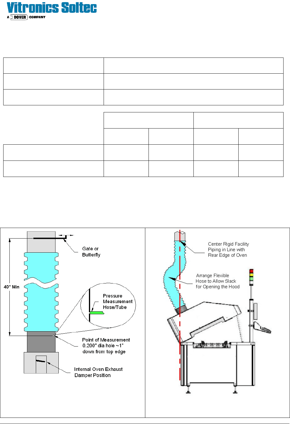
Exhaust Measurement Detail End View - Service Position Shown
Site Preparation & Installation Section: 2 Page: 14 Revision Date: April 2005
Exhaust Specifications (continued)
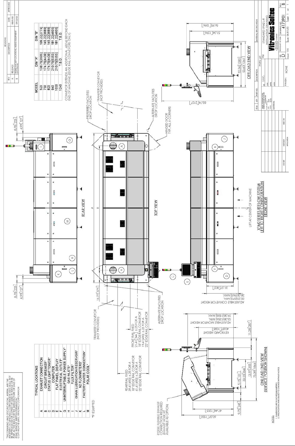
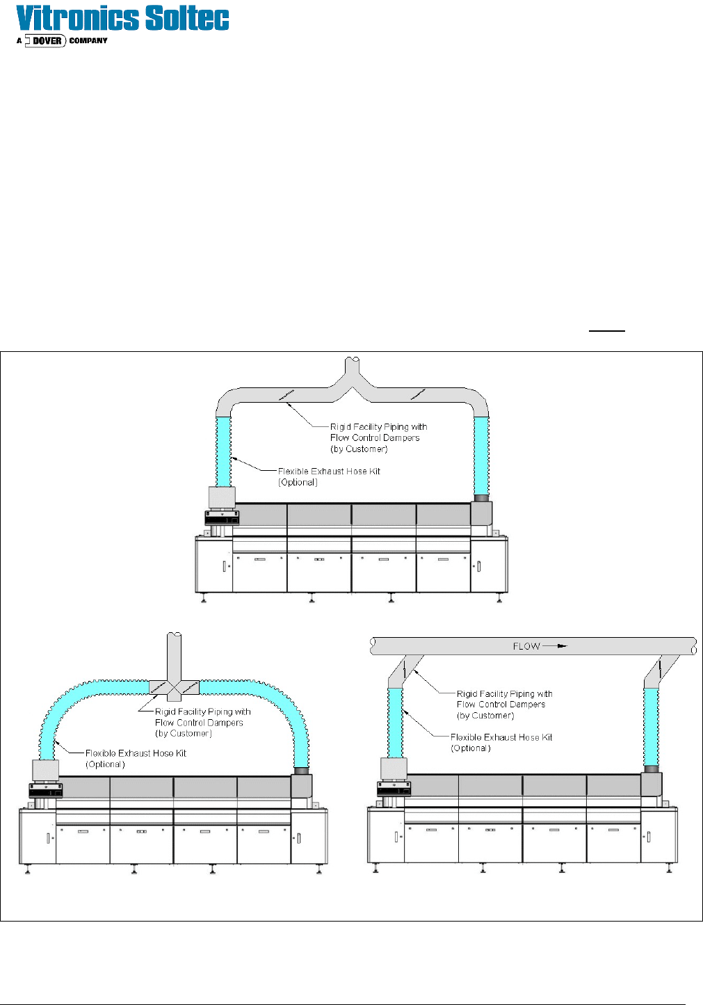
The oven requires one main facility exhaust connection branched into two sections and connected to
the exhaust ducts/ vents on the oven. The main facility drop should be offset to the rear of the oven by
approximately two feet. The connecting hose must be flexible and durable enough to allow for the
opening and closing of the Hood / upper heat zone for servicing. The installation of adjustable
dampers (as shown
below) in the exhaust connection is required to allow flow adjustments as necessary. Flow dampers
must be installed 40 inches above the top of the oven duct / vent. The Customer is responsible for
supplying the main exhaust drop, the two branch sections, flow dampers and hose clamps to connect
to the oven ducts/vents.
Adjustable dampers located approximately 40” (102 cm) above the oven duct / vent in each branch.
Examples of Acceptable Exhaust Configurations