XPM2-Site_Preparation - 第22页
Site Preparation & Installation Section: 2 Page: 22 Revision Date: April 2005 Connecting The Computer System The computer system mu st be set up and connected to t he oven. Unpack the computer, monitor, and keyboard …
Site Preparation & Installation Section: 2 Page: 20 Revision Date: April 2005
Unpacking the Oven
The XPM2 is a piece of large industrial equipment. Only qualified fork lift operators or
riggers should unpack, move, and position the oven. Keep fingers, hands and feet
clear at all times while lifting and positioning the oven.
CAUTION: Failure to follow the sequence described may result in injury or damage to the oven.
Ovens are shipped secured to a wooden
pallet (skid) and plastic wrapped. Where
required the oven may be crated and foil
bagged. If crated, remove the top section of
the crate first, the shorter end panels next
and the longer side sections last. Cut open
and remove the barrier bag and plastic
wrapping material. Remove the auxiliary
equipment boxes from the skid - be sure to
save the original packing material and boxes
in the event a return shipment may be
necessary for any reason.
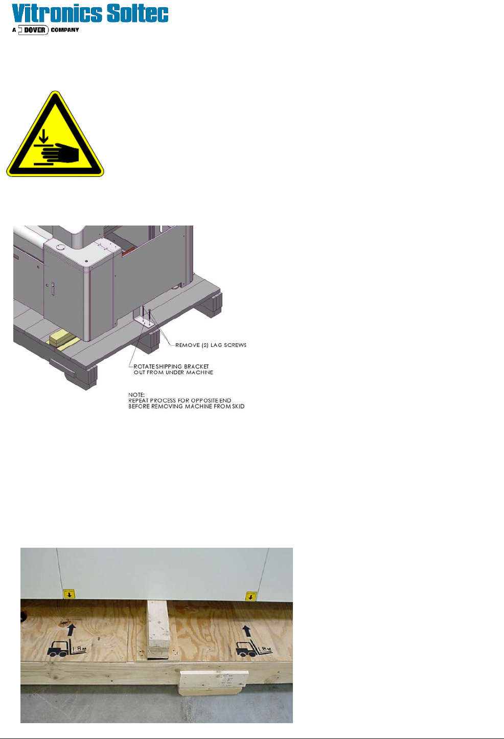
Unbolt and remove the shipping brackets (as
shown), located at the each end the skid/
oven before lifting the oven
Once the shipping brackets are unbolted and
removed from the oven and the area is
cleared of shipping material the oven may be
lifted with a fork truck and placed on movable
wheeled dollies capable of supporting the
oven's weight.
• Make sure the lifting forks are at least 6 feet (1.8 cm) long and enter from the rear of the oven only.
• Forks should be positioned to lift from the measured center of the oven.
Raise the oven high enough to allow the
skid to be removed from under the oven.
Make sure the oven is balanced properly
on the dollies before removing the fork
truck. On 7 and 10 zones oven s use two
dollies, one under each end. On 13 and
16 zone ovens use three dollies, one
under each end and one under a middle
crossmember to evenly support the oven
weight.
Site Preparation & Installation Section: 2 Page: 21 Revision Date: April 2005
Positioning & Pre-Leveling the Oven
Once the oven has been lifted from the shipping skid and placed securely on wheeled dollies, it may be moved
to the designated location. The leveling feet are not casters or wheels and may be damaged if the oven
is pushed or slid along the floor. The oven must be lifted and placed in position. Once in place, adjust
all of the feet down to an equal setting before the oven is removed from the dollies. This preliminary
adjustment assumes that the oven will be placed on a level floor surface. The oven may then be lifted with a
fork truck and set carefully in place. Make sure to position the lifting forks at the measured center of the oven.
For pre-leveling, the oven does not need to be lifted to adjust the height. The adjustable leveling feet are
designed and should be used as a jacking mechanism. The locking nut on each foot can be loosened and the
foot turned clockwise or counter-clockwise to raise or lower the oven.
The preliminary or pre-leveling operation requires a 2
foot level and tape measure.
1. Measure the transport height of the up / down
stream conveyors.
2. Start at the Onload (in-feed) end, adjust the oven
leveling foot at the front corner legs until the
conveyor height agrees with the transport height
of the up / down stream conveyors.
3. Place the level across the conveyor at the
Onload end of the oven and adjust the leveling
feet to level the conveyor across the Onload end.
4. Do the same for the Offload (out-feed) end of the
oven .
5. Once the Onload and Offload ends of the aligned
and leveled to the up / down stream conveyors, adjust the center leveling feet until pressure is felt with the
floor surface. When finished, all leveling feet must be firmly placed against the floor equally supporting the
oven weight.
6. The Vitronics Soltec Service Engineer will perform a final leveling procedure to ensure that the oven is
straight, flat, and free of twist
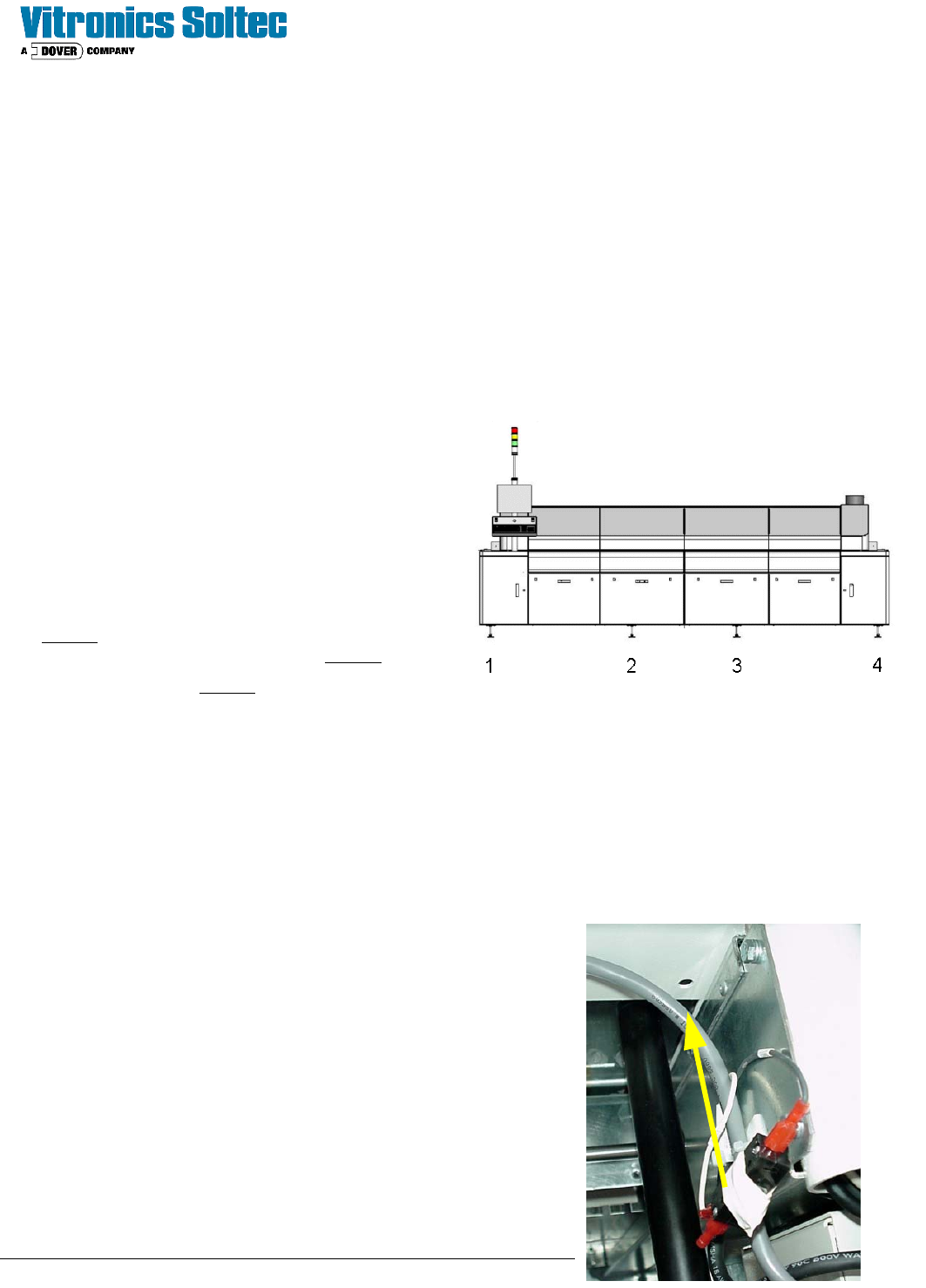
Connect the Hood Interlock Switch
The switch which detects if the hood position is down is removed from
its mounting location to avoid damage during shipping. This switch is
located behind the corner door located below the post for the monitor.
Remove the tape from the switch, remove the locking nut and insert
the switch through the hold shown. Replace the locking nut on top of
the cabinet to hold the switch into position. The switch is already
pre-wired.
Site Preparation & Installation Section: 2 Page: 22 Revision Date: April 2005
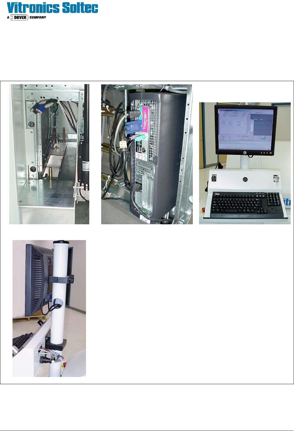
Connecting The Computer System
The computer system must be set up and connected to the oven. Unpack the computer, monitor, and keyboard
and place them on the tower as shown.
A B
C
D
A. The computer case is installed behind the corner door located
below the post for the monitor. All of the cables to be
connected to the rear of the computer are pre-wired to that
location.
B. Connect the cables for the power, monitor, data connection,
keyboard and mouse. Be sure cables are secured and will not
come in contact with any chains or belts inside of the oven.
C. Install the monitor and keyboard tray as shown. There is a
cover included for the bottom of the keyboard tray to enclose
the wiring.
D. The cables needed are prewired to the post. Make all
connections as shown.
If a light tower was ordered (as an option) install and connect it
to the top of the post at this time.
This completes the setup of the oven. You are now ready for a site visit by a Vitronics Soltec Service
Engineer to start up the equipment.