XPM2-Site_Preparation - 第7页
Site Preparation & Installation Section: 1 Page: 7 Revision Date: April 2005 6. GENERAL HAZARD LOCATIO NS The following illustrations ar e included to highlight the locations of some of the me chanical hazards. These…

Site Preparation & Installation Section: 1 Page: 6 Revision Date: April 2005
NITROGEN HAZARD: [if equipped] Follow the safety precautions and
procedures described in the Material Safety Data Sheet from the nitrogen
supplier. Nitrogen must be exhausted from the process area. If it is released in
within a confined space an oxygen deficiency will occur.
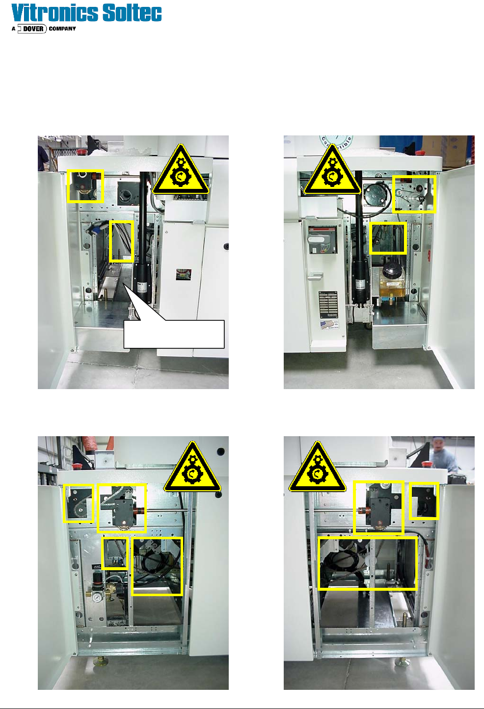
Site Preparation & Installation Section: 1 Page: 7 Revision Date: April 2005
6. GENERAL HAZARD LOCATIONS
The following illustrations are included to highlight the locations of some of the mechanical hazards.
These hazards can be exposed when the oven cover panels or doors are open for routine
maintenance or trouble shooting.
Shown With
Computer Removed
Front
Rear

Site Preparation & Installation Section: 1 Page: 8 Revision Date: April 2005
7. BUILT-IN SAFETY FEATURES
7.1.1. EMERGENCY STOP SWITCHES
The machine is fitted with emergency stop switches. The emergency stop has a red button
(mushroom type) and a yellow identification ring. The E-stop is a low voltage powered loop, that
provides automatic shut-down of any powered mechanism. When an E-stop is activated an
alarm message is displayed on the screen of the PC. When normal working condition is
restored, release the E-stop button, and reset the E-stop in the PC program.
7.1.2. LABELING OF HAZARDS
Labels are adhered to certain locations around the machine to alert the user to hazardous areas.
7.1.3. CIRCUIT BREAKERS
The machine is equipped with automatic circuit breakers and fuses, in case of a short-circuit or
overload the circuit will be cut off. Never use fuses or circuit breakers in the machine which are
not according the specifications from the electrical circuit diagrams.
7.1.4. COVERS
The machine is equipped with sheetmetal covers over the electrical enclosure and over most of
the mechanical components of the oven. A special key is required to open and remove these
covers.
Removing these covers while the oven is in operation can expose the user to rotating parts and
high voltage.
7.1.5. GUARDS
The machine is equipped with safety guards covering the rotating portions of the conveyor end
assemblies. These guards must remain in place during operation.
7.1.6. BONNET CONTROL SWITCH
A spring loaded keyswitch is located on the operator control panel to activate the linear actuators
which raise the bonnet. The operator must remain at the control panel position while the
actuators are moving. Releasing the keyswitch will stop the movement of the bonnet.
7.1.7. ALARMS
The machine is equipped with software alarms to alert the operator to a machine condition that
is not normal to the process. These alarms may be audible or visual depending on the situation.
Refer to the Oven Alarm Levels section of the Operation Manual for the proper response level to
each type of alarm.
7.1.8. MAIN DISCONNECT (OPTION)
A machine mounted and lockable power disconnect is available to shut down all power to the
machine for certain service operations.
7.1.9. EXHAUST INTERLOCK (OPTION)
A pressure switch located within the exhaust stack is provided and connected to the control
circuitry which will activate an alarm condition if the exhaust pressure falls outside of the
setpoint.
7.1.10. LIGHT TOWER (OPTION)
A multi color light tower is available to provide quick reference to the operational status of the
machine and alert the user to situations which may cause damage to the product or machine.