00197623-03_VD_708.1_SP2_DE_EN.pdf - 第11页
Station Software 7 08.1 SP2 / Version Description Ausgabe 10/2015 E dition 11 In the CAP ta b, data related t o the Diagnosis M as ter is displayed. The power sup plies ( SMPS ) and fuses ( 24V , 27V etc.) can be selecte…
Station Software 708.1 SP2 / Version Description Ausgabe 10/2015 Edition
10
5.3 Power Supply (SMPS) – Status Display on the GUI
Compatible mode: Complete
The SMPS (Switched Mode Power Supply) offers advanced diagnostic checks. As of this station
software version, the SMPS states are additionally displayed on the GUI.
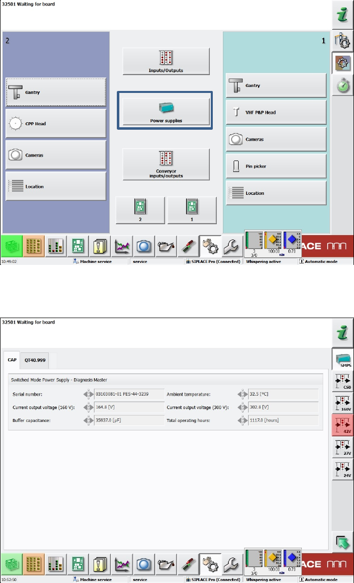
As of the Machine Service activity level, the new Power supplies button is available under
Manual operations – Subsystems.
Figure 5-1: Subsystems dialog – Power supplies
If this button is selected, a new dialog opens in which the states of the power supplies and fuses
are displayed.
Figure 5-2: Diagnosis Master dialog – CAP tab
Station Software 708.1 SP2 / Version Description Ausgabe 10/2015 Edition
11
In the CAP tab, data related to the Diagnosis Master is displayed.
The power supplies (SMPS) and fuses (24V, 27V etc.) can be selected to the right. The fuses are
grouped by their respective voltage.
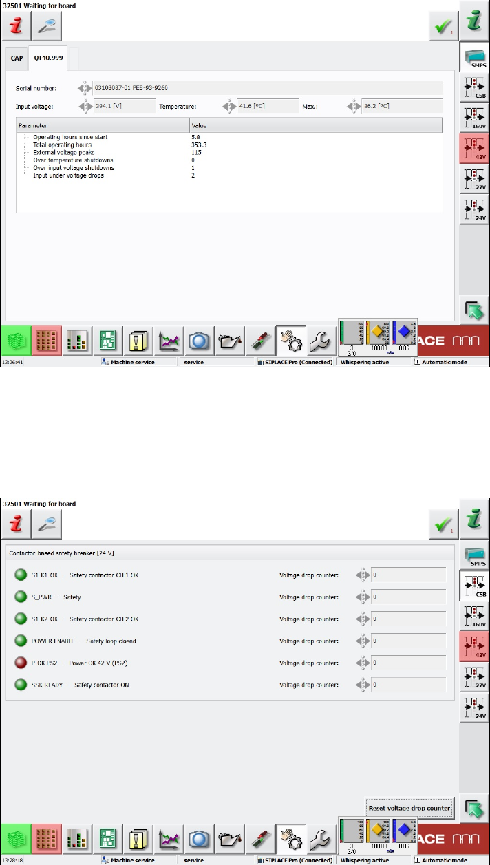
Figure 5-3: Diagnosis Master dialog – SMPS tab
In the SMPS tab (here: QT40.999), data related to the respective power supply is displayed. There
may be two tabs, one for each possibly existing power supply. If only one power supply exists, the
second tab is disabled.
Sensors related to the safety circuit of the machine are grouped in the CSS view (Contactor-based
Safety Switch-off) to the right.
Figure 5-4: CSS view
Station Software 708.1 SP2 / Version Description Ausgabe 10/2015 Edition
12
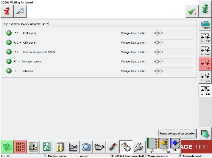
If a fuse group is selected (here 24V), a corresponding view is displayed.
Figure 5-5: Fuse group view
The states of the assigned fuses are displayed in the following colors:
Gray: switched off
Green: switched on
Red: faulty
One long name and one short name are displayed for each fuse. The short names are the same as
those in the figures of the real hardware that can be found in the Online help of the station
software.
Additionally, the number of voltage drops since the last reset is displayed. The counter for all
displayed fuses can be reset with the Reset voltage drop counter button.
5.4 WDTL – Multiple Set-up Components in Barcode Controlled
Production with Synchronous Dual Lane Mode
Compatible mode: Not supported
The station software now supports multiple set-up components in barcode controlled production
with synchronous dual lane mode. Multiple set-up components means that the components are set-
up on more than one station.
In synchronous dual lane mode, each of the two boards gets the same unique ID for the SIPLACE
Pro job in the first station. This ID will be transferred by WDTL through the line.
If boards with the same ID are moved together into another station, the boards will be placed
together with the same SIPLACE Pro job. This is the usual case.
If boards with different IDs are moved together into another station, the boards will be separated
and separately placed in asynchronous mode.