00197623-03_VD_708.1_SP2_DE_EN.pdf - 第17页
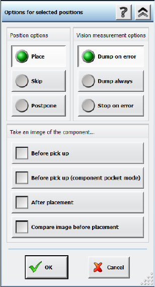
Station Software 7 08.1 SP2 / Version Description Ausgabe 10/2015 E dition 17 Figure 5-9: Placement error analy sis options After this option ha s been selected for o ne or several plac ement position s, the placement pr…
Station Software 708.1 SP2 / Version Description Ausgabe 10/2015 Edition
16
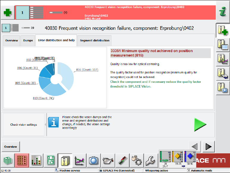
In the Error distribution and help tab a diagram displays all errors. If an error is selected by
clicking on it, corresponding help assistance is displayed to the right.
Figure 5-8: Frequent Vision errors – Error distribution and help tab
In the Segment distribution tab the same diagram is displayed but additionally with the counter
for the respective segment.
5.11 Enhanced Placement Error Analysis
Compatible mode: Complete
In the Board view, an inspection option can be selected for each placement position. A Vision
image can be taken of the components before pickup and after placement on the board and the
dump files can be stored. However, with these analysis options it is not possible to differentiate if
the placement problem occured on the way to the placement position, during placement or after
placement. For this, an inspection of the component position is required for one or several
placement positions immediately before the placement process takes place (before the z-axis is
started for placement).
The diagnosis functionality in the Board view has been enhanced by the Compare Image before
placement option.
Station Software 708.1 SP2 / Version Description Ausgabe 10/2015 Edition
17
Figure 5-9: Placement error analysis options
After this option has been selected for one or several placement positions, the placement process
is interrupted before the z-axis starts to place the component and a new measurement with
reduced acceleration is started. The reduced acceleration shall prevent further slippage of the
components. After the additional measurement, the component is brought to the placement
position with reduced acceleration and will be placed with the z-axis acceleration that is defined in
SIPLACE Pro.
The two measurements (standard and before placement) can be compared and evaluated via the
inspection function for Vision measurements on the GUI. A possible slippage of the component can
thus be clearly recognized. Additionally, the results of the additional measurement are entered in
the board history files. This allows a statistical analysis over a longer period.
5.12 Robust Dual Gantry Measurement
Compatible mode: Complete
The dual gantry measurement procedure has been improved.
In a dual gantry configuration, the station software performs a dual gantry measurement every 5
minutes in order to correlate the gantries' positions and correct the positions, if necessary. Until
now, if a fiducial was manually taught or the wrong fiducial was detected by one of the gantries, the
resulting error was applied to all boards produced within the next 5 minutes.
To prevent such process errors, the dual gantry correction will now not be transferred to the next
board(s) if any of the fiducial positions were taught by the operator. This includes all cases in which
the first fiducial measurement failed and the operator intervened via a detailed error. Instead, a new
dual gantry measurement will be performed for the next board.
Station Software 708.1 SP2 / Version Description Ausgabe 10/2015 Edition
18
5.13 Enhancements in SIPLACE Vision
The SIPLACE Vision system has been enhanced as follows:
– Displaying a virtual keyboard
Compatible mode: Compatible
SIPLACE Vision automatically displays a virtual keyboard on the GUI of the station software
whenever a text entry field has been selected. This behavior has to be configured in the station
software beforehand.
The virtual keyboard is not displayed on the GUI of the Vision Teach Station because a
keyboard is always available in this case.
– Modifications to allow reading of individual barcode fiducials by the board camera.
Compatible mode: Complete
– Improved procedure to teach the pickup position if the camera is outside the travel range due to
a slight rotation.
Compatible mode: Compatible
– If connection problems occur in the communication with the GigE cameras, the errors are
narrowed down by specific queries and detailed error messages displayed.
Compatible mode: Complete
– Correction in the calculation of the scaling of MFU components.
Compatible mode: Complete