DEK高级培训资料.pdf - 第64页
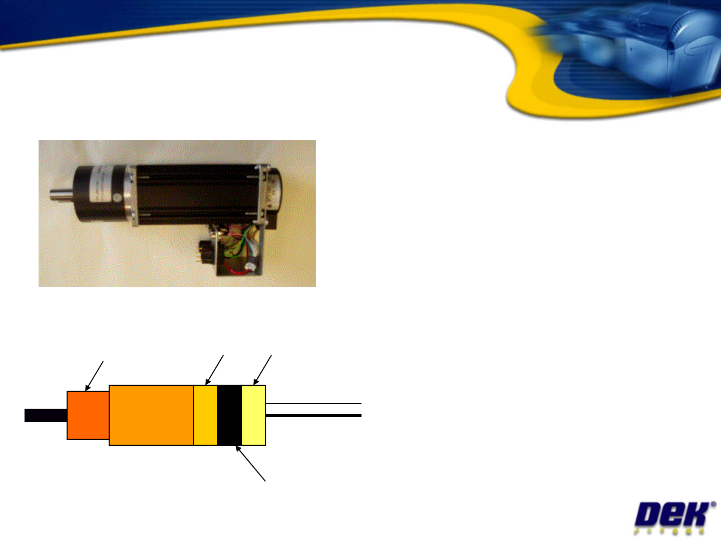
• Single unit includes servo motor , drive electronics, encoder , processor and CANopen interface CANopen servo motor Issue 2: July 2007 interface • Units are connected via CAN bus • Camera ‘X’ (Rotary machines) • Camera…

Sensors tasks
•
Monitor the signal output of the camera ‘Y’
home sensor using the diagnostics software
•
Measure the supply voltage at the camera Y
home sensor
Issue 2: July 2007
home sensor
•
Measure the signal voltage output from the
sensor in both on and off states
•
Repeat the tasks above for the rail lifted right
sensor
•
Is there a difference? If yes why?
Task: Complete the details in your workbook
•
Single unit includes
servo motor, drive
electronics, encoder,
processor and CANopen
interface
CANopen servo motor
Issue 2: July 2007
interface
• Units are connected via
CAN bus
•
Camera ‘X’ (Rotary
machines)
•
Camera ‘Y’ (Rotary
machines)
•
Print Carriage
Servo Motor
Drive
electronics
Processor
CANopen
interface
CAN Bus
DC Power
Gearbox
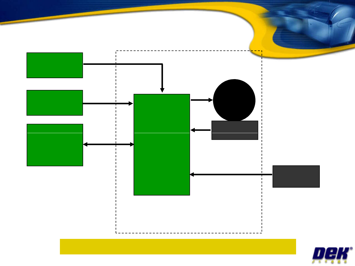
Servo motor block diagram
MOTOR
______
V =
V =
Servo Power
PSU __
Logic Supply
PSU __
Print Carriage
_____ ______
________
__________
Issue 2: July 2007
______
CANSERVO MOTOR MODULE
Objective 9: Complete the diagram in your workbook
_____ ______
_____ __
_______
________
__________
_ _