X-S Speicification - 第36页
36 Component Feeding Matrix Tray Changer (MTC) Technical Data Electrical ratings To w e r 1 ( X L ) To w e r 2 Dimensions Length x width Height 1305 mm x 600 mm 1560 mm for 900 mm PCB conveyor height 1590 mm for 930 mm P…
35
Component Feeding
Matrix Tray Changer (MTC)
If you need to provide com-
ponents in multiple waffle
pack tray for the placement
process, we recommend
using an automatic maga-
zine changeover with the
help of an Matrix Tray
Changer (MTC).
In SIPLACE X3 S/X4 S
machines, an MTC can be
docked onto location 2 in
place of the component
trolley. The service flap in
the machine protection of
the SIPLACE X3 S/X4 S
placement machine provides
access to the front section of
the feed axis.
The MTC setup is coordi-
nated to the exact placement
sequence to achieve a path-
optimized and time-opti-
mized working process. Two
towers with waffle pack trays
move independently of one
another, in a vertical direc-
tion, until the required maga-
zine reaches the access area
of the feed axis. The horizon-
tal feed axis transports the
waffle pack tray from the
tower to the access area of
the placement head. The first
magazine is made available
as soon as a board is moved
into the PCB conveyor and
valid panel and setup data
has been provided.
All other magazine changes
are executed during the
placement process without
influencing the processing
time. JEDEC magazines can
be refilled without stopping
the machine. Faulty compo-
nents are placed back in the
original magazine.
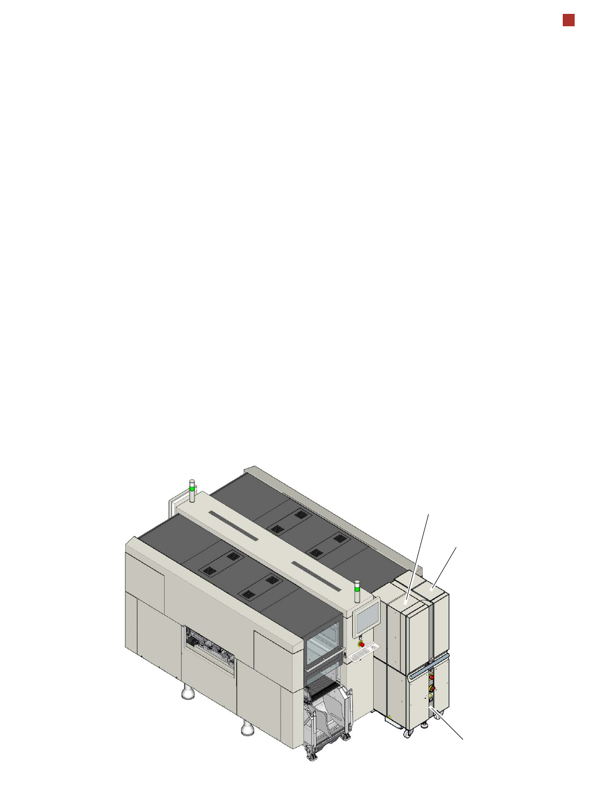
Tower 2
Tower 1
MTC

36
Component Feeding
Matrix Tray Changer (MTC)
Technical Data
Electrical ratings
Tower 1 (XL) Tower 2
Dimensions
Length x width
Height
1305 mm x 600 mm
1560 mm for 900 mm PCB conveyor height
1590 mm for 930 mm PCB conveyor height
1640 mm for 950 mm PCB conveyor height
Weight (basic package)
approx. 500 kg (with cassettes and waffle pack tray carriers)
Weight (fully configured)
approx. 534 kg (with components)
Weight (moving loads)
approx. 80 kg approx. 43.5 kg
Cassette size (L x W x H)
391.2 x 305.6 x 93.3 mm³ 352.7 x 154.8 x 133.8 mm³
Cassette weight
(fully configured)
(without waffle pack tray carrier)
approx. 11 kg
approx. 1.7 kg
approx. 7.5 kg
approx. 1.35 kg
Weight of the waffle pack tray
carrier
850 g 150 g
Dimensions of waffle pack tray
carrier (L x W x H)
386.5 mm x 295.8 mm x 11.1 mm 371 mm x 146 mm x 10.1 mm
Distance from cassette to cas-
sette
96 mm 135 mm
Distance from level to level
12 mm 11.8 mm
Storage capacity
30 waffle pack tray carrier XL with
60 JEDEC or
30 special magazines
of maximum size
40 waffle pack tray carriers
with 40 JEDEC waffle pack
trays
Changeover time (over 5 levels)
approx. 2 s approx. 1.5 s
Max. height of component and
waffle pack tray incl. tolerances
All levels occupied
One level free
Two levels free
8.5 mm
19.5 mm
31.5 mm
8.5 mm
19.5 mm
–
Supply voltage 3 x 400 V~, 50 Hz (Europe)
3 x 208 V~, 60 Hz (USA)
Overall power 1.5 kW
Apparent power 3.85 kVA
Rated current 2.7 A at 3 x 400 V~
4.2 A at 3 x 208 V~
Fuse 3 x 16 A
Rated current consumption of largest con-
sumer
2 A

37
Digital SIPLACE Vision System
The digital Vision system
ensures fast and reliable
component recognition, cou-
pled with user-friendly han-
dling. The system identifies
each individual component
by its geometry and color.
Even complex component
shapes, such as flip chip or
CCGA are detected with high
reliability.
This component recognition
check is performed in a sin-
gle step, with no extra time
involved but with optimum
scanning of each individual
component.
This digital Vision system is
not only used in the compo-
nent cameras but also in the
PCB camera. In addition to
the precise recognition of
components, this also guar-
antees reliable detection of
ínkspots and PCB fiducials.
The benefits at a glance:
• Extremely fast and reliable
component recognition
• Shortest cycle times
• Robust measurement
based on the geometry
and color
• Straightforward program-
ming
• Offline programming of
component shapes
• Rapid introduction of new
products (NPI)
• Open architecture allows
you to quickly adapt to
new requirements
• Optimum placement
results based on individ-
ual measurement of each
component
The SIPLACE Vision sys-
tem offers inspection rou-
tines and functions to
enhance the quality of com-
ponent recognition.
The benefits at a glance:
• Maximum placement
quality
• High first pass yield
• Reduction of operating
costs
Examples of digital vision system analysis times
Evaluation times only play a role in the P&P process.
01005 9 ms
PLC44 17 ms
BGA 225 balls 18 ms
Digital vision cameras
SIPLACE SpeedStar camera, type 23
SIPLACE SpeedStar camera, type 41
SIPLACE MultiStar camera, type 30
SIPLACE TwinStar standard camera, type 33
SIPLACE TwinStar high resolution camera, type 25
SIPLACE PCB camera, type 34