SM482PLUS_Maintenance(Eng_Ver2.7).pdf - 第17页
Chap ter 1 This Chapter describes the work environment and working tools for the maintenance of the machine. Conditions fo r Main t e nanc e Multi -Func tional Placer SM482PLUS Maintenance Handbo ok 1-8 W orking Environm…
Chapter 1
This Chapter describes the work environment and working tools for the maintenance of
the machine.
Conditions for Maintenance
Multi-Functional Placer
SM482PLUS Maintenance Handbook
1-7
Working Environment and Condition
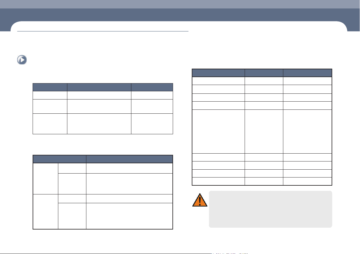
Requirements for air pressure
DEF. DESCRIPTION Notes
Primary pressure 5.0 - 7.0 kgf/cm
2
Secondary
pressure
4.5 - 5.5 kgf/cm
2
Air Consumption 180 NL/min ±20 %
Vacuum Pump: 50 ±20 % NL/
min(Option)
5 kgf/cm
2
(Secondary
pneumatic standard)
Environmental conditions
DEF. DESCRIPTION
During
operation
Temperature v
Humidity
30 % - 80 % RH (non-condensation state)
Lessthan70%RH(Morethan30℃,non-
condensation state)
During
shipment or
storage (in
states other
than during
operation)
Temperature -10℃-60℃
Humidity
10 % RH - 90 % RH (non-condensation state)
Morethan35℃(Lessthawet-bulbtemperature
35℃,non-condensationstate)
Power requirements
DEF. DESCRIPTION Notes
Capacity Max. 3.5 kVA
Frequency 50/60Hz
Phase 3 Phase
Connection Y-Y
Rated Primary Voltage AC 200 ± 18 V
AC 208 ± 19 V
AC 220 ± 20 V
AC 240 ± 22 V
AC 380 ± 25 V
AC 415 ± 28 V
Permitted Voltage Drop(s)
Short Circuit Current Rating 100 KA (220 VAC)
Distribution System TN
Full-Load Current 20 A Full Load Ampere
Peak Starting Currents -
Warning
If unspecified voltage is used or power input is changed
improperly, fire could occur and a death from electric shock could
occur.
Change of power input must be done by a trained repair and
maintenance operator or our authorized C/S personnel.
Working Environment and Condition
Chapter 1
This Chapter describes the work environment and working tools for the maintenance of
the machine.
Conditions for Maintenance
Multi-Functional Placer
SM482PLUS Maintenance Handbook
1-8
Working Environment and Condition
Conditions for Maintenance
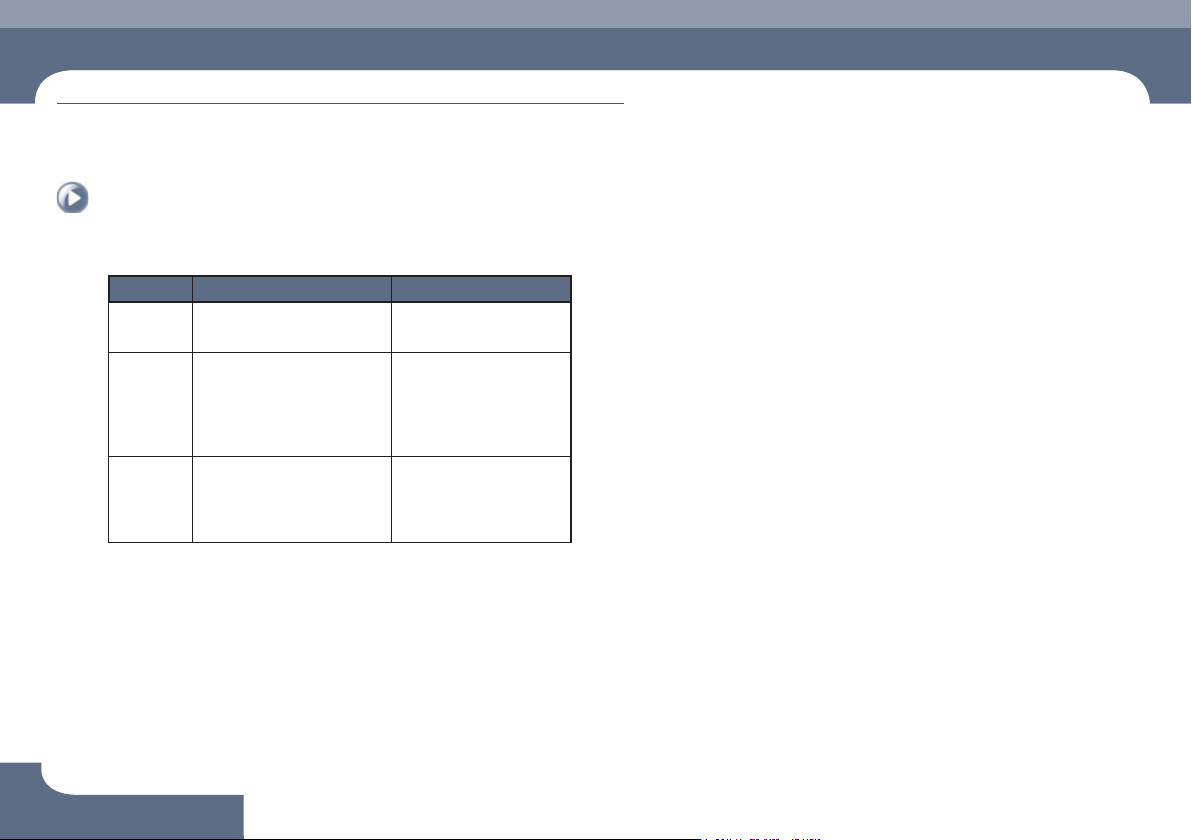
Installation requirements
DEF. DESCRIPTION Notes
Height 900 ± 20 mm or
952.5 ± 12.5 mm
ㆍ Based on the top of the
PCB transfer belt
Leveling Simultaneous measurement at
3 locations
ㆍ Level gauge graduation
Right and left Deviation 0.05
mm/M within graduation
ㆍ Y1 LM Guide Top Center
ㆍ Y2 LM Guide Top Center
ㆍ Front FeederBase Center
Cooling
system
Secure space in front of the
cooling fan
ㆍ 2 places at the bottom of
the left side
ㆍ 2 places at the bottom of
the right side
Chapter 1
This Chapter describes the work environment and working tools for the maintenance of
the machine.
Conditions for Maintenance
Multi-Functional Placer
SM482PLUS Maintenance Handbook
1-9
Tools for Maintenance
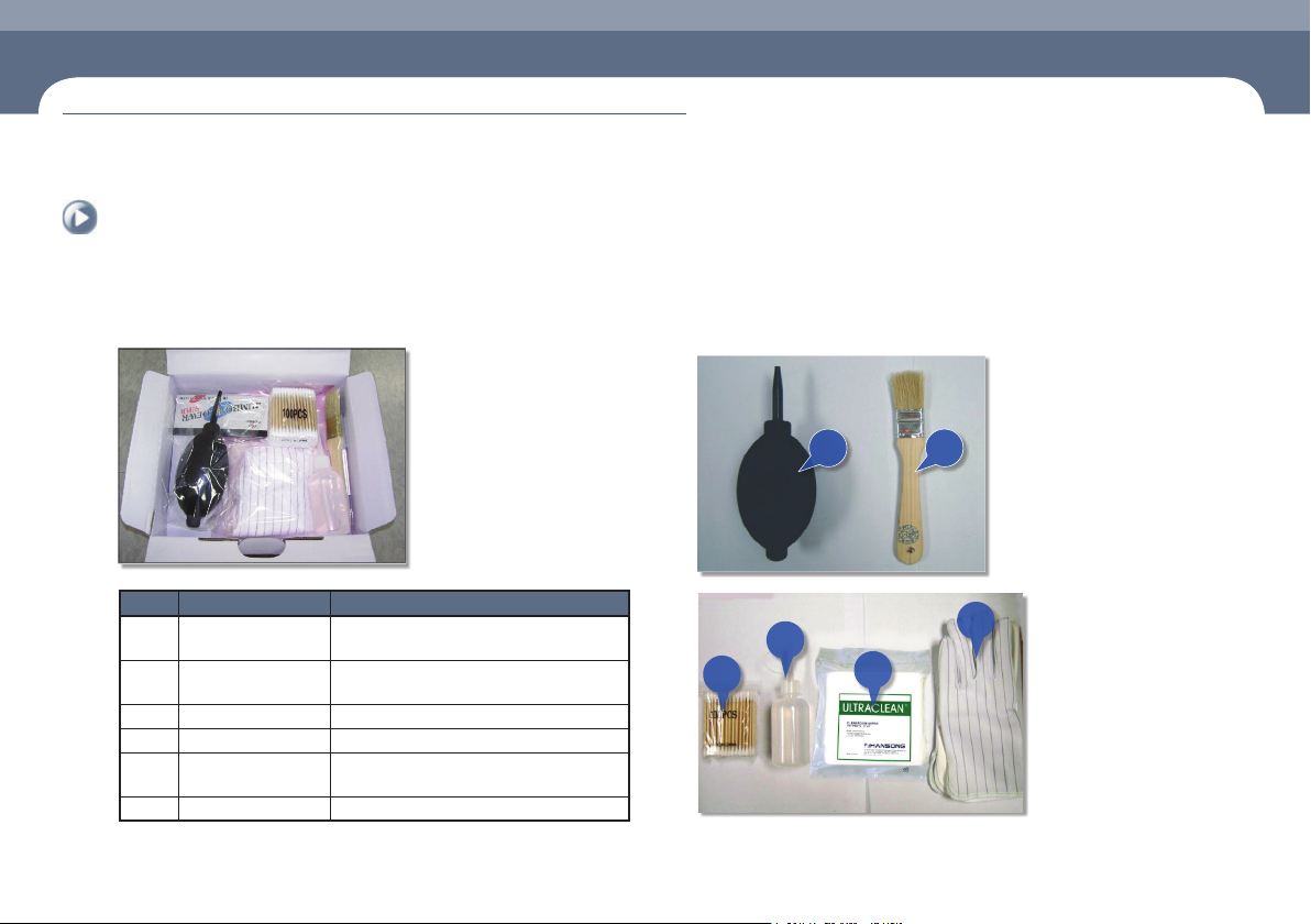
1. Cleaning Kit (Material shape: FC08-001021A)
The Cleaning Kit for the maintenance of this machine must be purchased separately.
The components of the cleaning kit and their use are as follows:
NO. NAME DESCRIPTION
1 Air Ejector
Used to blow away any dirt on the surface of
the camera lens.
2 Brush
Used to remove any chips or foreign matter
on the feeder base surface.
3 Swab Used to clean the nozzle holder.
4 alcohol Used to clean the cover glass surface.
5 Ultra-fine fiber cloth
Used to clean any foreign matter on the
mirror or lens.
6 Embossed glove Used to clean the camera or mirror.
1 2
3
4
5
6
Tools for Maintenance