HS50的结构及原理.pdf - 第114页
6 Gantries Adjustment Instructions S IPLACE HS-50 6.4 Settings and Illustrations Edition 05/00 114 .(< (1) Component c amera (2) Video signals PCB came ra (3) Illum inatio n PCB c amer a (4) Limit swit ch x-axis (5)…
Adjustment Instructions SIPLACE HS-50 6 Gantries
Edition 05/00 6.4 Settings and Illustrations
113
6HWWLQJVDQG,OO XVWUDWLRQV
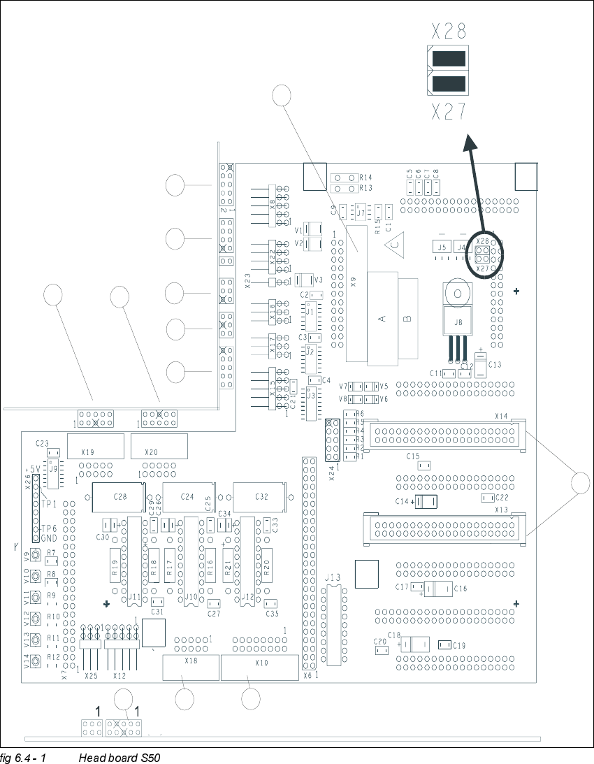
-XPSHU6HWWLQJVRQ+HDG%RDUG6
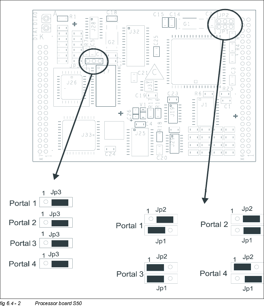
Portal 1 / gantry 1
Portal 2 / gantry 2
Portal 3 / gantry 3
Portal 4 / gantry 4
6 Gantries Adjustment Instructions SIPLACE HS-50
6.4 Settings and Illustrations Edition 05/00
114
.(<
(1) Component camera
(2) Video signals PCB camera
(3) Illumination PCB camera
(4) Limit switch x-axis
(5) Limit switch x-axis
(6) Track signals x-axis
(7) Ejection of valve drive
(8) Placement of valve drive
(9) Motor / tacho dp - station
(10) Swivel - in motor, dp - station
(11) Vacuum test board
(12) Intermediate distributor SP 6 - 12, digital
Adjustment Instructions SIPLACE HS-50 6 Gantries
Edition 05/00 6.4 Settings and Illustrations
115
-XPSHU6HWWLQJV3URFHVVRU%RDUG6
R12
R19
R24
R20
R23
R22
R21
R12
C10
C9
R11
R10
R 9
R8
R15
R14
R13
C13
C12
C11
C13
C12
C11