HS50的结构及原理.pdf - 第129页
Adjustment Instructions SIPLACE HS -50 6 Gantries Edition 05/00 6.6 Calibration of the Anti - Cr ash Board 129 &DOLEUDWLRQRIWK H$ QWL &UDVK%RDUG 7 HVW(TXLSPHQW – Digital m ultime ter – SITEST so…
6 Gantries Adjustment Instructions SIPLACE HS-50
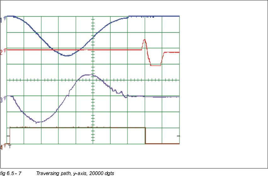
6.5 Dynamic Adjustment of the X- and Y- Axes Edition 05/00
128
Sollwert /
Vnominal
Positionsabweichung /
deviation of position
Stromsollwert /
nominal current
Endemeldung /
end signal
Adjustment Instructions SIPLACE HS-50 6 Gantries
Edition 05/00 6.6 Calibration of the Anti - Crash Board
129
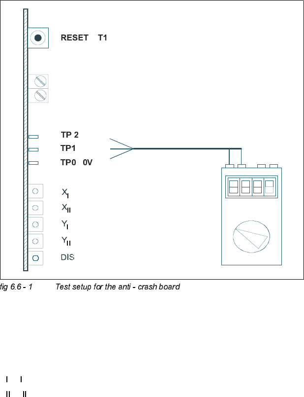
&DOLEUDWLRQRIWK H$QWL &UDVK%RDUG
7HVW(TXLSPHQW
– Digital multimeter
– SITEST software
– Anti - crash board for HS-50
7HVW6HWXS
.(<
TP2 = Signal
R82, R92 = Potentiometer
TP1 = Signal
X
, Y = "Error" message for the axes of the left gantry in each work area.
X
, Y = "Error" message for the axes of the right gantry in each work area.
(Viewpoint from input conveyor).
DIS = Message: Distance sensor activated.
R 82
R 92

6 Gantries Adjustment Instructions SIPLACE HS-50
6.6 Calibration of the Anti - Crash Board Edition 05/00
130
NOTE
Adjustments are identical for both gantry groups.
CAUTION
Perform these adjustments only after you pressed the EMERGENCY STOP button!
$GMXVWPHQWRI'LVWDQFH6HQVRU6HQVLWLYLW\
Å Connect the digital multimeter of the anti - crash board to pin TP 0 (0V) and pin TP 1 (signal).
Å Move both gantries together.
Å Use the adjusting screw to set the voltage at the distance sensor to 6V - +/- 0,1 V.
Å Move the two gantries together until a distance of 100 mm is reached.
(Elastomer spring up to opposite plane).
– The voltage must reach a value of approx. 2V.
&DOLEUDWLRQRIWKH$QWL&UDVK%RDUG
Å Connect the digital multimeter to the anti - crash board at pin TP2 (signal) and pin TP0 (0V).
Å Move both gantries together.
Å Use the potentiometer R82 to adjust the voltage to 0V- +/- 0.05 V.
Å Move the two gantries together until a distance of 100 mm is reached.
Å Use the potentiometer R92 to adjust the voltage to 10V- +/- 0.05 V.
Å Check the 0V- setting one more time.
Å Repeat the calibration if the reached value is incorrect.
)XQFWLRQ&RQWURORIWKH'LVWDQFH6HQVRU
3UHSDUDWLRQ
Å Perform a reference run.
7HVWLQJ3ODFHPHQW$UHDV,DQG,,
Å In placement area I, attach a piece of paper in the middle of the machine, at the height of the
distance sensor.