HS50的结构及原理.pdf - 第142页
7 Collect & Place Head DLM1 Adjustment I nstructions SIPLACE HS-50 7.3 Adjustments Edition 05/00 142 $ GMXVWPHQW V RI WKH $ LU 3UHVVXUH 9 DOXHV Z LWK WKH +HOS RI D &RPSUHVVHG $LU 7 HVWLQ J &…
Adjustment Instructions SIPLACE HS-50 7 Collect & Place Head DLM1
Edition 05/00 7.3 Adjustments
141
$LU3UHVVXUH9DOXHV
7RROVDQG'HYLFHV
– A set of slotted screw drivers
– Compressed air testing device
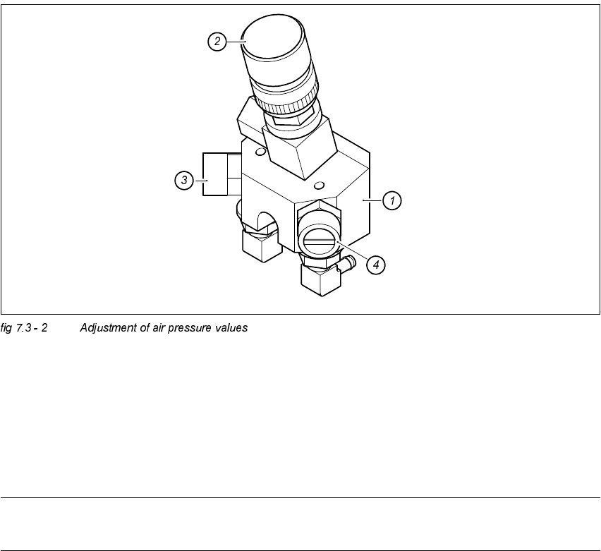
$GMXVWPHQWRI$LU3UHVVXUH9DOXHV
.(<
(1) Forced air unit / DLM1
(2) Micro - relay valve
(3) Restrictor valve for the reject circuit
(4) Restrictor valve for the pick - up / placement circuit
NOTE
Use a nozzle type 914 to adjust the blast air.
7 Collect & Place Head DLM1 Adjustment Instructions SIPLACE HS-50
7.3 Adjustments Edition 05/00
142
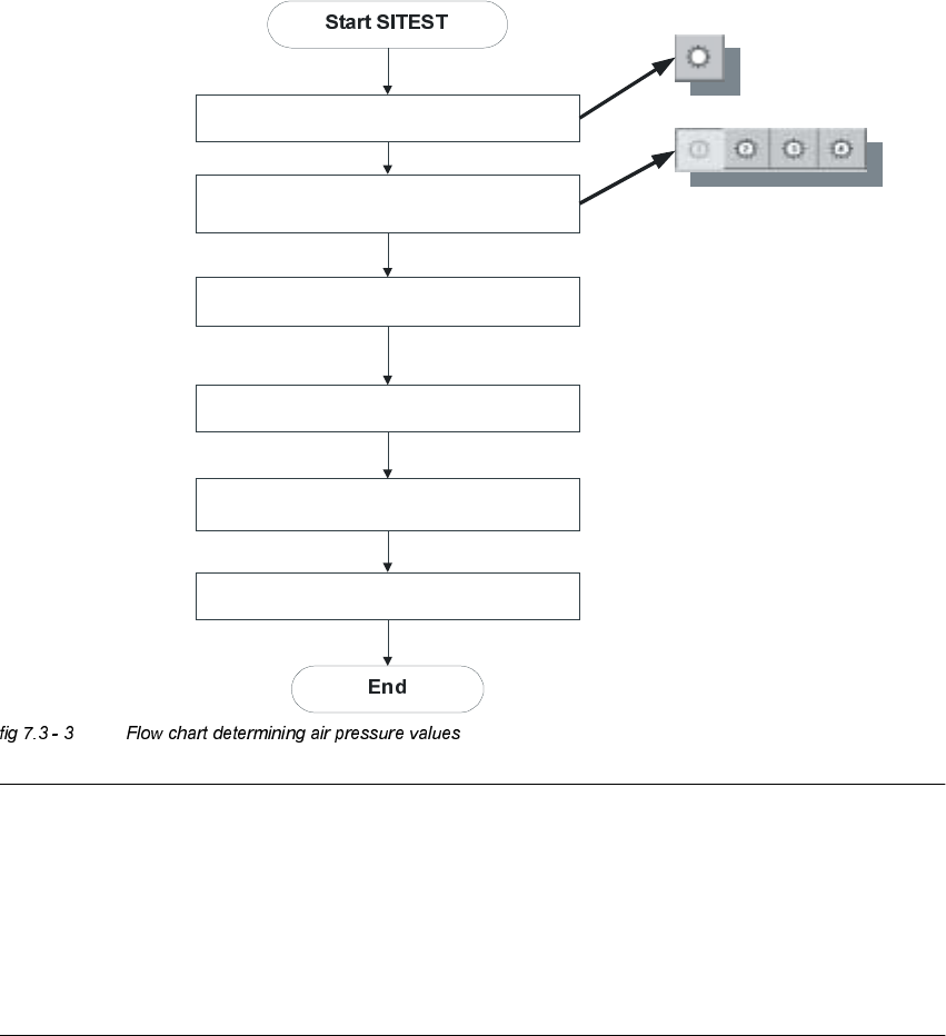
$GMXVWPHQWVRIWKH$LU3UHVVXUH9DOXHVZLWKWKH+HOSRID&RPSUHVVHG$LU7HVWLQJ
'HYLFH
NOTE
Air pressure values, displayed on the screen of the station computer, under option "Measure air
pressure" of the "Single functions", or in the SITEST program, do not correspond to the air
pressure values actually set at the nozzles.
They solely serve to check that the forced air valve is functioning correctly.
Therefore, the air pressure may not be adjusted with the values displayed on the screen.
Instead, use only the values determined with the compressed air testing device.
Blast air “ON”
Placement and pick - up circuit
Select appropriate head
Collect & Place Heads
Use compressed air testing device and
restrictor valve to adjust compressed air
Blast air “OFF”

Adjustment Instructions SIPLACE HS-50 7 Collect & Place Head DLM1
Edition 05/00 7.3 Adjustments
143
Å Adjust to the values of the table below:
NOTE
Both forced air circuits are controlled by a single valve and therefore are mutually dependent.
Using two different restrictor valves (compare item 3 and 4 in fig 7.3 - 2), it is however possible, to
adjust differing pressure values for each circuit.
Å Repeat these adjustments several times, as the pick - up / placement circuit are mutually
dependent.
NOTE
Make sure that the test sensor tube is attached air - tight on the nozzle.
56)'LJLWDO5RWDU\7UDQVGXFHURI'3$[LV
56)'LJLWDO7UDQVGXFHURI'3$[LV
Å Remove sleeve 1 and insert the star zero point gauge, in order to mechanically fix the star.
Å Now, remove sleeve 4 as well and align the transducer.
Å With the help of a parallel pin, set the digital transducer of the dp - axis to 1.5 mm, parallel to
the glass pane of the segment.
NOTE
A parallel pin of 1.4 mm must easily fit through the gap, a parallel pin of 1.6 mm must be too big
to fit.
)RUFHG$LU9DOXHV
$GMXVWPHQWZLWK&RPSUHVVHG$LU
7HVWLQJ'HYLFH
0HDVXUHPHQWWDNHQRQ1R]]OH
'LVSOD\HGRQWKH0RQLWRU
2QO\LQ3LFN8SDQG3ODFHPHQW
&LUFXLW
pick - up / placement
circuit 150 mbar (100 - 200 mbar) e.g.: 250 mbar
reject circuit 250 mbar (200 - 300 mbar) reject cicuit does not have a sensor