HS50的结构及原理.pdf - 第145页
Adjustment Instructions SIPLACE HS-50 7 Collect & Place Head DLM1 Edition 05/00 7.3 Adjustments 145 2WKHU0HFKDQLFDO$ GMXVWPHQWVRQWKH6W DU Å Insert t he blast a ir transi tion tu bes so th at they wil l pro…
7 Collect & Place Head DLM1 Adjustment Instructions SIPLACE HS-50
7.3 Adjustments Edition 05/00
144
/LJKW%DUULHU%RWWRP3RVLWLRQ
NOTE
In order to adjust the light barrier, use a parallel pin and adjust it to a distance of 1.33 mm to the
sleeve.
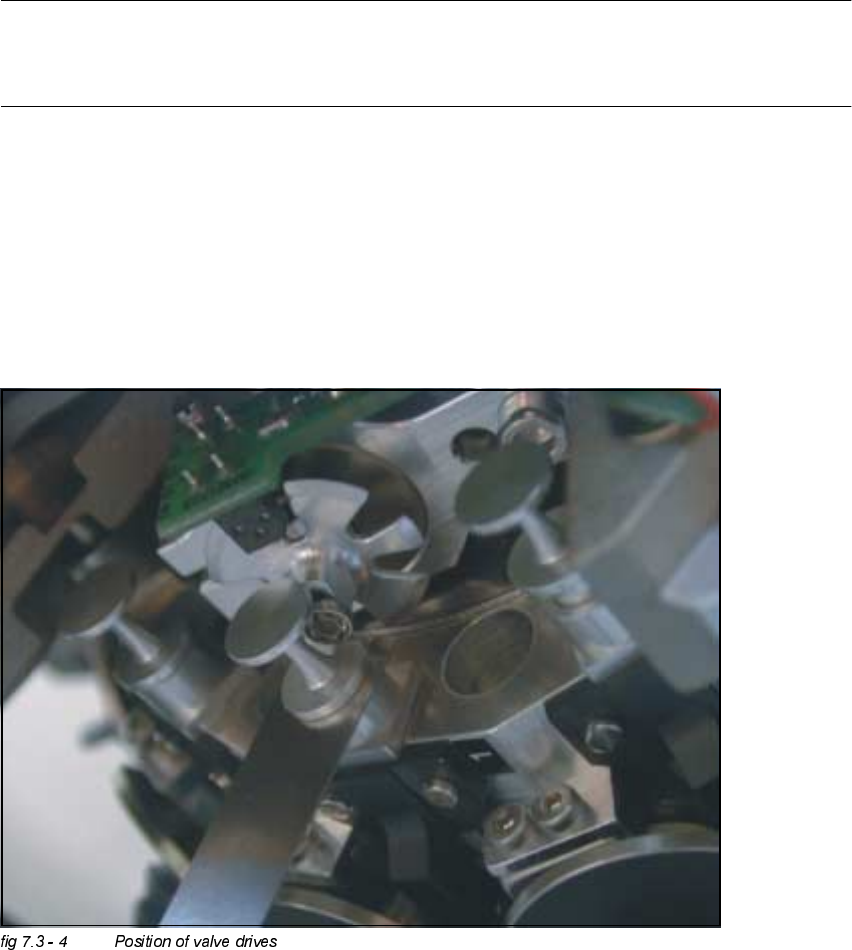
$GMXVWPHQWRI0HFKDQLFDO3RVLWLRQRI9DOYH'ULYHV
Å Set the motor position of the valve drives "Pick-up / Placement" and "Ejection" according to the
figure below.
Å Insert the distance gauge between valve plunger and valve casing.
Å Turn the valve drive to 90° degrees, opposite to its initial position.

Adjustment Instructions SIPLACE HS-50 7 Collect & Place Head DLM1
Edition 05/00 7.3 Adjustments
145
2WKHU0HFKDQLFDO$GMXVWPHQWVRQWKH6WDU
Å Insert the blast air transition tubes so that they will protrude 0.5 mm from the surface of the
circular arc guide.
NOTE
The blast air tubes at the valve plungers should be at a distance of 0.2 mm from the encoder
of the dp - axis.
7 Collect & Place Head DLM1 Adjustment Instructions SIPLACE HS-50
7.4 Dynamic Adjustment of the Axes Edition 05/00
146
'\QDPLF$GMXVWPHQWRIWKH$[HV
NOTE
Gantry 1 serves to exemplify all SITEST functions.
7RROVDQG7HVW$ LGV
– 2 or 4 channel storage oscilloscope.
– SIPLACE axis test box.
–SITEST software.
NOTE
The machine must have reached its operating temperature before you begin to adjust the axes.
Therefore, make sure to switch it on, at least 30 minutes before you begin to work.
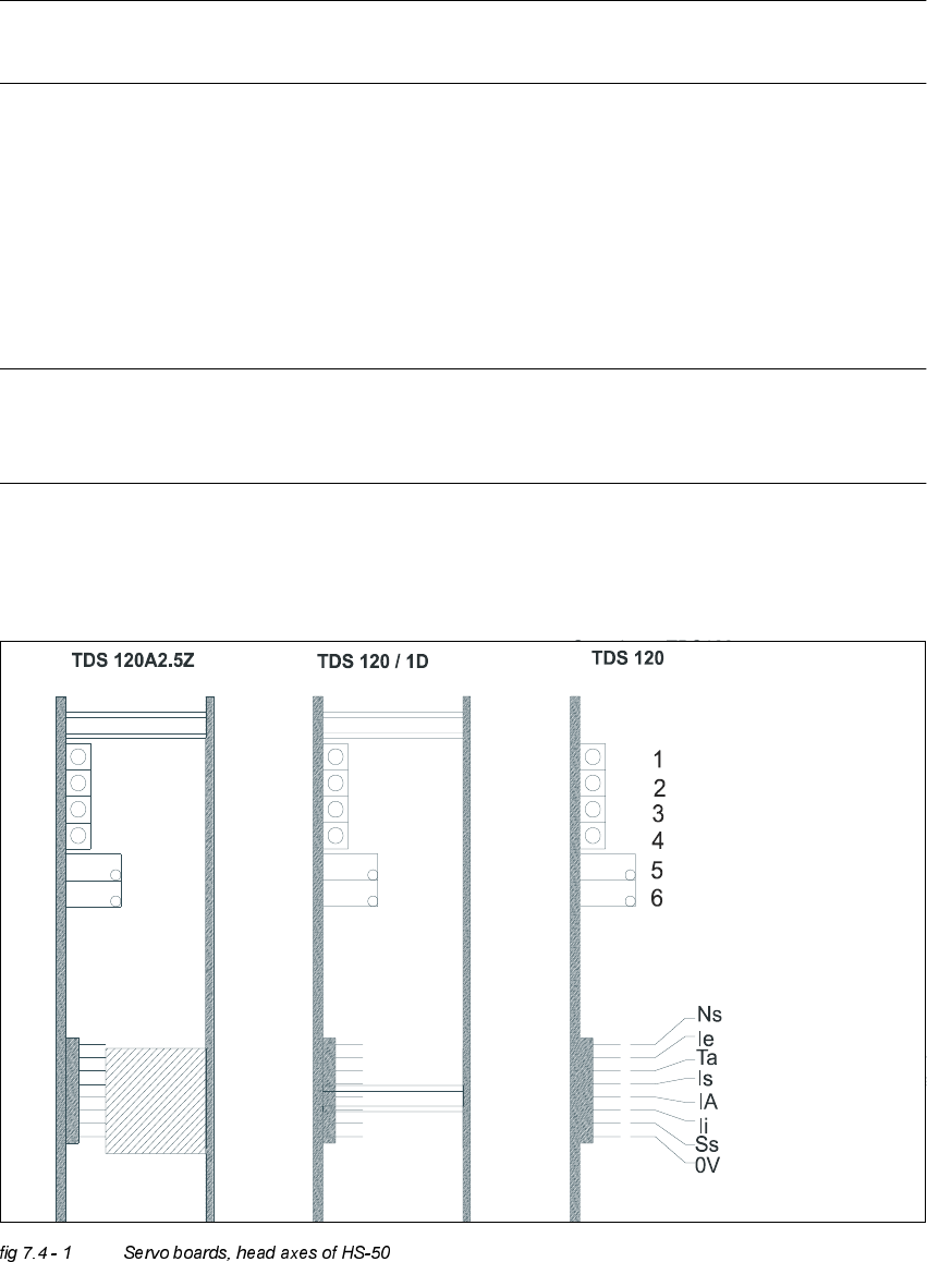
6HUYR%RDUG+HDG$[HV+6