HS50的结构及原理.pdf - 第149页
Adjustment Instructions SIPLACE HS-50 7 Collect & Place Head DLM1 Edition 05/00 7.4 Dynamic Ad justment of the Axes 149 2YHUY LHZ RI$ [HV&RQWURO&DUGV+6 type of a xis and ga ntry number adress o…
7 Collect & Place Head DLM1 Adjustment Instructions SIPLACE HS-50
7.4 Dynamic Adjustment of the Axes Edition 05/00
148
.(<
(1) LED: Ready for operation
(2) LED: Enable output stage
(3) LED: I
RMS
limit
(4) LED: Error
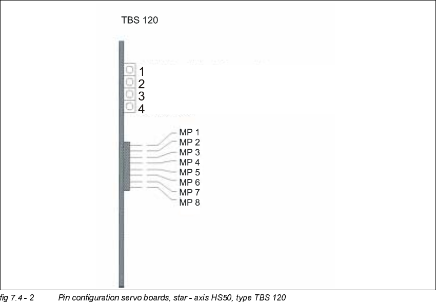
MP1 = Nominal current "I-S (U)"
MP2 = Nominal current "I-S (W)"
MP3 = Actual current "I-ist (U)"
MP4 = Actual current "I-ist (W)"
MP5 = "U-nominal (U)"
MP6 = "U-nominal (W)"
MP7 = Free
MP8 = Reference potential "0V"
Adjustment Instructions SIPLACE HS-50 7 Collect & Place Head DLM1
Edition 05/00 7.4 Dynamic Adjustment of the Axes
149
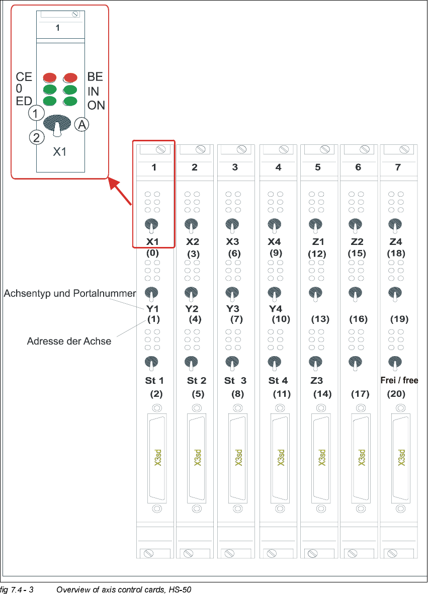
2YHUY LHZ RI$[HV&RQWURO&DUGV+6
type of axis and gantry number
adress of axis
'3 '3
'3
'3
CE = Counting error
0 = Zero pulse
ED = End signal
BE = General error, module error
IN = Initialized
ON = Servo ON
(A) Axis enable switch
(1) Servo ON
(2) Servo OFF
7 Collect & Place Head DLM1 Adjustment Instructions SIPLACE HS-50
7.4 Dynamic Adjustment of the Axes Edition 05/00
150
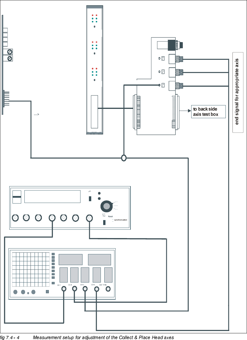
0HDVXUHPHQW6HWXSIRU$[LV$GMXVWPHQWV
ready for operation
enable output stage
effective current limit
error
tacho
P-gain
axis 0
axis 1
axis 2
measuring current of star - axis
changeover switch pressed down
end signal axis 0
end signal axis 1
end signal axis 2
interface
test adapter
axis test box
actual current
with RC - filter
current measuring of dp - axis and z-axis only
interface axis control card
interface axis test box
track A track B zero pulse Vnom force end signal deviat. of pos.
dgt
zero pulse
end signal
axis 0
axis 1
axis 2
OFF
ON
Vnominal
d
e
via
tio
n
o
f p
o
sitio
n
cu
rre
n
t va
lu
e
e
n
d
s
ig
n
a
l