HS50的结构及原理.pdf - 第159页
Adjustment Instructions SIPLACE HS-50 7 Collect & Place Head DLM1 Edition 05/00 7.4 Dynamic Ad justment of the Axes 159 2VFLO ORVFRS H6H WWLQ JV – If the dyna mics o f the z-axis are set corr ectly , a time of 73 …
7 Collect & Place Head DLM1 Adjustment Instructions SIPLACE HS-50
7.4 Dynamic Adjustment of the Axes Edition 05/00
158
2VFLOORVFRSH6HWWLQJVIRUWKH=$[LV8SZDUG
&KHFNRI =$[LVZLWK6WDQGVWLOO&RQWURO
6,7(67
Å Select "C&P Heads" ==> "Select head" ==>
"Axis functions" ==> "Select axis" ==> "Adjust P-gain" ==>
"Edit and accept values: Positioning time downward = with standstill control; positioning mode
upward = absolute".
Å If necessary, press the START button.
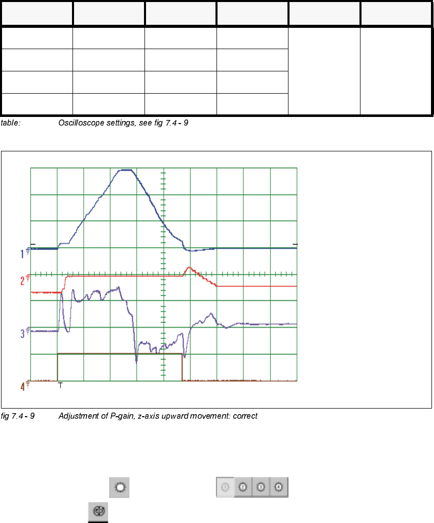
&KDQQHO 6LJQDO &RXSOLQJ <'HIOHFWLRQ 7ULJJHU ;'HIOHFWLRQ
CH1 Vnominal DC 2.0 V/ DIV
CH 1
negative
10% pre
5 ms/ DIV
CH2 deviat. of pos DC 1.0 V/ DIV
CH3 actual current DC 5.0 V/ DIV
Ch4 end signal DC 5,0 V/ DIV
Sollwert /
Vnominal
Positionsabweichung /
deviation of position
Stromistwert /
actual current
Endemeldung /
end signal
Adjustment Instructions SIPLACE HS-50 7 Collect & Place Head DLM1
Edition 05/00 7.4 Dynamic Adjustment of the Axes
159
2VFLOORVFRSH6HWWLQJV
– If the dynamics of the z-axis are set correctly, a time of 73 ms + / - 10 ms until the end signal
will be reached. (See above).
'S$[LV
*HQHUDO3UHSDUDWLRQV
Å Start SITEST.
Å Turn on the compressed air supply.
Å Prepare the measurement setup for the star-axis acoording to fig 7.4 - 4.
Å Set the oscilloscope according to the table below.
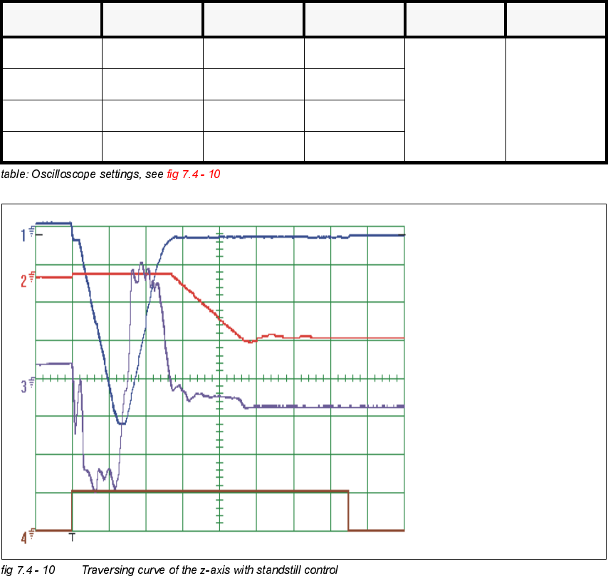
&KDQQHO 6LJQDO &RXSOLQJ <'HIOHFWLRQ 7ULJJHU ;'HIOHFWLRQ
CH1 Vnominal DC 1.0 V/ DIV
CH 1
negative
10% pre
10 ms/ DIV
CH2 deviat. of pos DC 2.0 V/ DIV
CH3 actual current DC 2.0 V/ DIV
CH 4 end signal DC 5.0 V/ DIV
Sollwert /
Vnominal
Positionsabweichung /
deviation of position
Stromistwert /
actual current
Endemeldung /
end signal
7 Collect & Place Head DLM1 Adjustment Instructions SIPLACE HS-50
7.4 Dynamic Adjustment of the Axes Edition 05/00
160
Å Perform a head reference run.
NOTE
Use an RC - filter to record the current curve
In order to measure the actual current on the servo amplifier, connect only the actual current and
no *1'.
Measure the end signal on the measuring adapter of the axis control card, with the switch
activated.
(IIHFWVRI3*DLQ6HW7RR+LJKRU7RR/RZ
NOTE
If the P-gain is set too low, the deviation of position will sag and the end signal will be prolonged.
If the actual current is set too high, the end signal will be prolonged as well, the actual current and
the deviation of position will oscillate however.
$GMXVWPHQWRI7DFKRWR9
6,7(67
Å Select "C&P Heads" ==> "Select head ==>
"Axis functions" ==> "Select dp - axis" ==> "Tacho adjustment".
Å Use the potentiometer "Tacho" on the servo board to adjust the displayed value on the station
monitor to 0V +/- 10 mV.