HS50的结构及原理.pdf - 第166页
166 9 Calibration of SIPLACE HS-50 (incl. SITEST version 501.xx) Adjustment Instructions HS-50 9.1 Preparations for Calibration Software-Version 5.01 Edition 05/00 5 4 3 2 1 10 9 8 7 6 5 4 3 2 1 10 9 8 7 6 6 7 8 9 10…

9 Calibration of SIPLACE HS-50 (incl. SITEST version 501.xx) Adjustment Instructions HS-50
Software-Version 5.01 Edition 05/00
165
WARNING
During some of the procedures the gantries will traverse.
Therefore, before you begin with any of these procedures make sure that you and everyone else stay
physically clear of the travel range of the gantries. 5,6.2),1-85<
Also, ascertain, that no objects are in the way.
NOTE
Before you begin with the calibration, you must reference the heads and the gantries.
During calibration, unused gantries will automatically be traversed to their parking position.
For a complete calibration of the placement system, the SITEST test program provides the function
&DOLEUDWHPDFKLQH which allows you to start all calibration functions from the menu "Calibrate entire
machine".
Calibration functions will be performed for these functions, for gantries 1, 2, 3 and 4.
(TXLSPHQWDQG7HVWLQJ7RROV
– Test program SITEST, version 501.xx
– Calibration tools
– Nozzles, type 956
– Gauge
– PCB, width 100 mm
&DOLEUDWLRQRI6,3/$&(+6
LQFO6,7(67YHUVLRQ[[
166
9 Calibration of SIPLACE HS-50 (incl. SITEST version 501.xx) Adjustment Instructions HS-50
9.1 Preparations for Calibration Software-Version 5.01 Edition 05/00
5
4
3
2
1
10
9
8
7
6
5
4
3
2
1
10
9
8
7
6
6
7
8
9
10
1
2
3
4
5
6
7
8
9
10
1
2
3
4
5
2
3
4
5
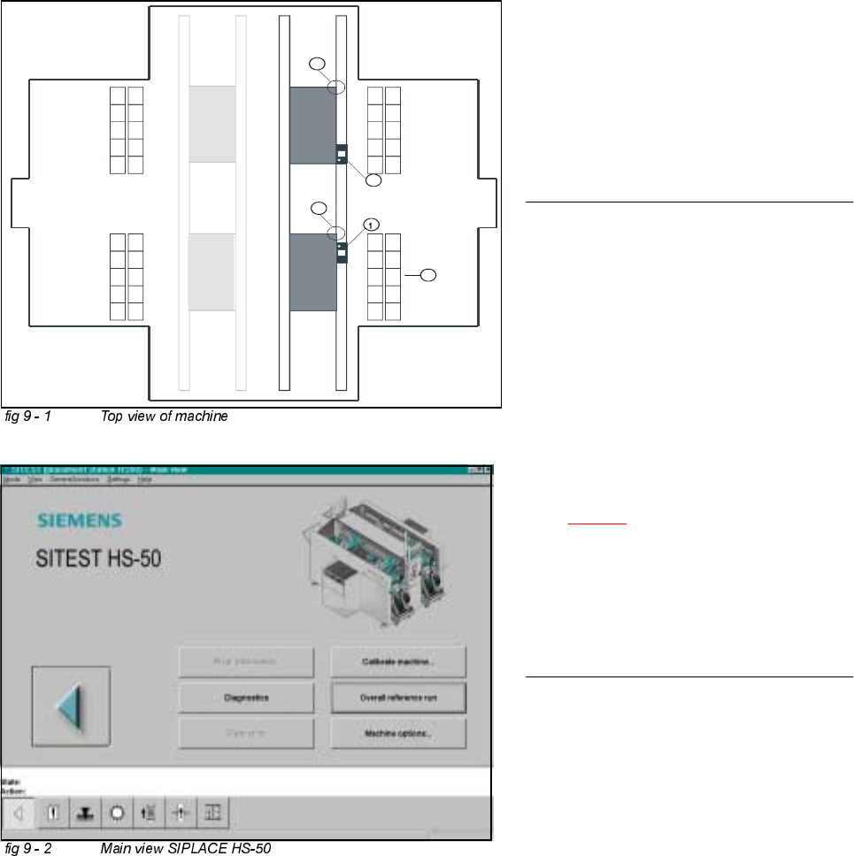
.(<
(1) Calibration tool, placement position 1
(2) Fixed PCB corner
(3) Nozzle changer magazine
(4) Placement area 2
(5) Placement area 2
NOTE
Some calibrations require that you attach
ozzles on the placement heads.
Use nozzles of type .
Make sure that all nozzles have been
attached correctly, otherwise measuring
will lead to incorrect results.
If you need to, place the calibration tool
into the "calibration bag".
(See fig 9 - 1
).
Before you place the calibration tool, make
sure that it is clean. Also, be sure that you
insert it into the "calibration bag" with its
print of the fiducial structure on the bot-
tom.
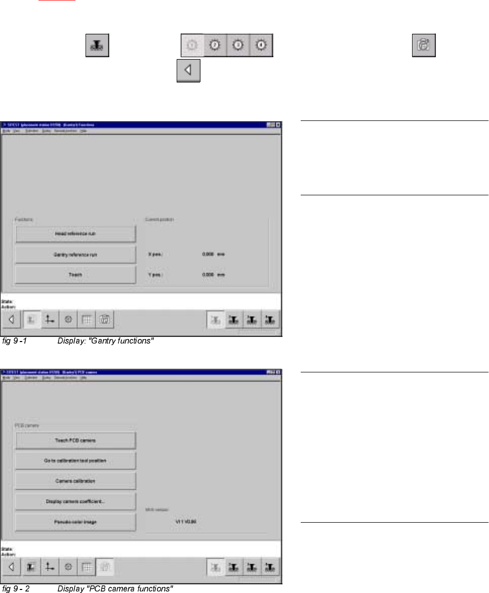
3UH SDUDWLRQVIRU&DOLEUDWLRQ
Å Start SITEST.
Å Under menu item "Main view", click "Overall reference run", to reference all gantry- and head- axes.
Adjustment Instructions HS-50 9 Calibration of SIPLACE HS-50 (incl. SITEST version 501.xx)
Software-Version 5.01 Edition 05/00 9.2 Calibration of PCB - Camera
167
&DOLEUDWLRQRI3&%&DPHUD
Example: PCB - camera, gantry 1
Å Insert the calibration tool into the "calibration bag 1" in placement area 1.
(See
fig 9 - 1).
6,7(67
Å Select "Gantry" ==> "Gantry 1" ==> "PCB - camera functions" ==>
"Calibrate camera" ==> "Main view" ==> "Save machine data".
NOTE
Repeat these instructions in order to
calibrate the PCB - cameras of gantries
2, 3 and 4.
NOTE
With the help of the function "Display
camera coefficient", the determined
values can be displayed after you finished
calibration.
The value under "Angle [1 / 100°] must not
exceed 100.