HS50的结构及原理.pdf - 第169页
Adjustment Instructions HS-50 9 Calibration of SIPLACE HS-50 (incl. SITEST version 501.xx) Software-Version 5.01 Edition 05/00 9.4 Calibration of Machine Zero P oint 169 &DOLEUDWLRQRI 0 DFKLQH=HUR3RLQ W E…
168
9 Calibration of SIPLACE HS-50 (incl. SITEST version 501.xx) Adjustment Instructions HS-50
9.3 Calibration of the Collect & Place Head Software-Version 5.01 Edition 05/00
NOTE
Repeat these instructions in order to
calibrate the C&P Heads 2, 3 and 4.
For the calibration follow these steps:
– Calibration of the PCB - camera
– Calibration of the C&P - camera
– Determination of the segment offsets I
for all 12 segments
– Determination of the segment offsets II
for all 12 segments and the C&P
PCB camera offset, relating to
segment I.
NOTE
With the help of the function "Display
camera coefficient", the determined val-
ues can be displayed after you finished
calibration.
Segment offset I: No deviation > 120 µm
between the individual segments and no
value for a single segment > 450 µm
allowed!
Segment offset II: The value for segment 1
is always 0.
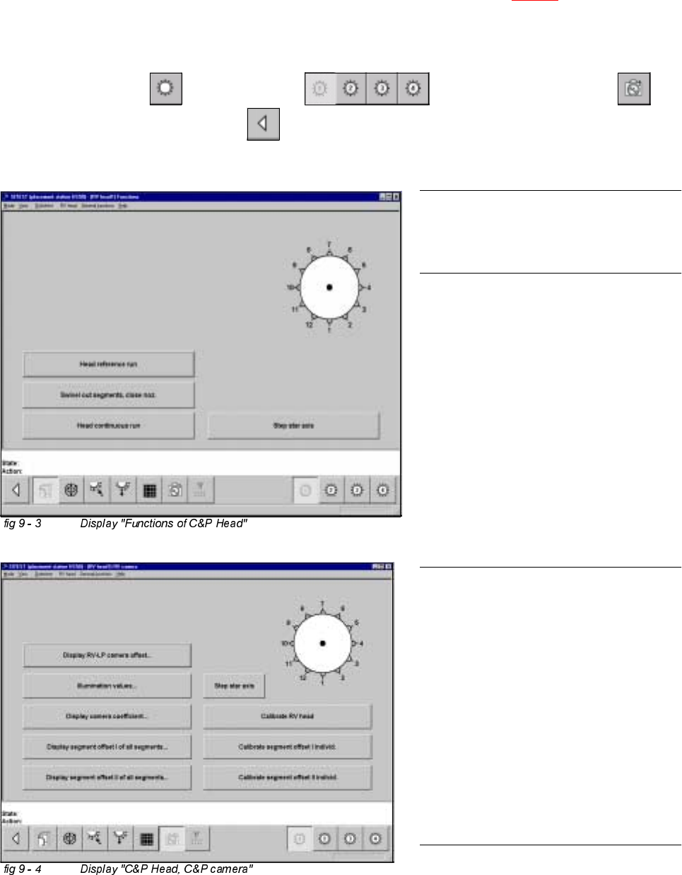
&DOLEUDWLRQRIWKH&ROOHFW3ODFH+HDG
Example: C&P Head 1
Å Insert the calibration tool into the "calibration bag 1" in placement area 1. (See fig 9 - 1).
Å Place 12 nozzles, type 956 on the star.
6,7(67
Å Select "C&P Heads" ==> "C&P Head 1" ==> "C&P Head and camera" ==>
"Calibrate camera" ==> "Main view" ==> "Save machine data".
Adjustment Instructions HS-50 9 Calibration of SIPLACE HS-50 (incl. SITEST version 501.xx)
Software-Version 5.01 Edition 05/00 9.4 Calibration of Machine Zero Point
169
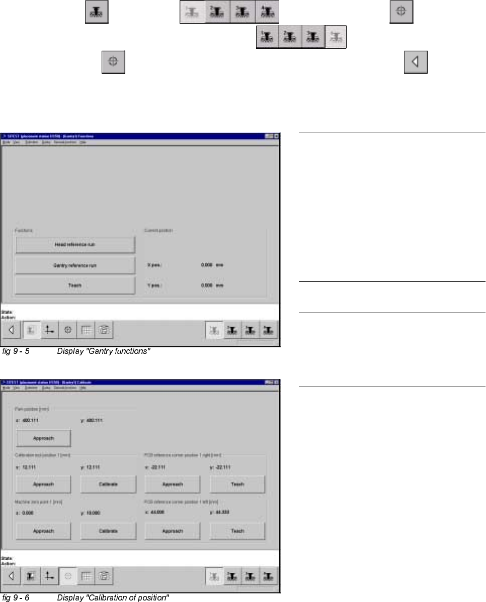
&DOLEUDWLRQRI0DFKLQH=HUR3RLQW
Example: Placement area 1.
6,7(67
Å Select "Gantry" ==> "Gantry 1" ==> "Calibrate position" ==>
"Calibrate (field "Machine zero point")" ==> "Gantry 4" ==>
"Calibrate position" ==> "Calibrate (field "Machine zero point 1")" ==> "Main view" ==>
"Save machine data".
NOTE
Make sure that all calibration data for the
C&P camera, the segment offset II (C&P -
PCB camera offset) and the PCB camera
have been determined.
The calibration of the machine zero point
must be performed with both gantries
each in placement area 1 or 2,
respectively.
NOTE
Proceed the same way with gantries 2 and
3, in order to determine the machine zero
point in placement area 2.
170
9 Calibration of SIPLACE HS-50 (incl. SITEST version 501.xx) Adjustment Instructions HS-50
9.5 Calibration of Calibration Position Software-Version 5.01 Edition 05/00
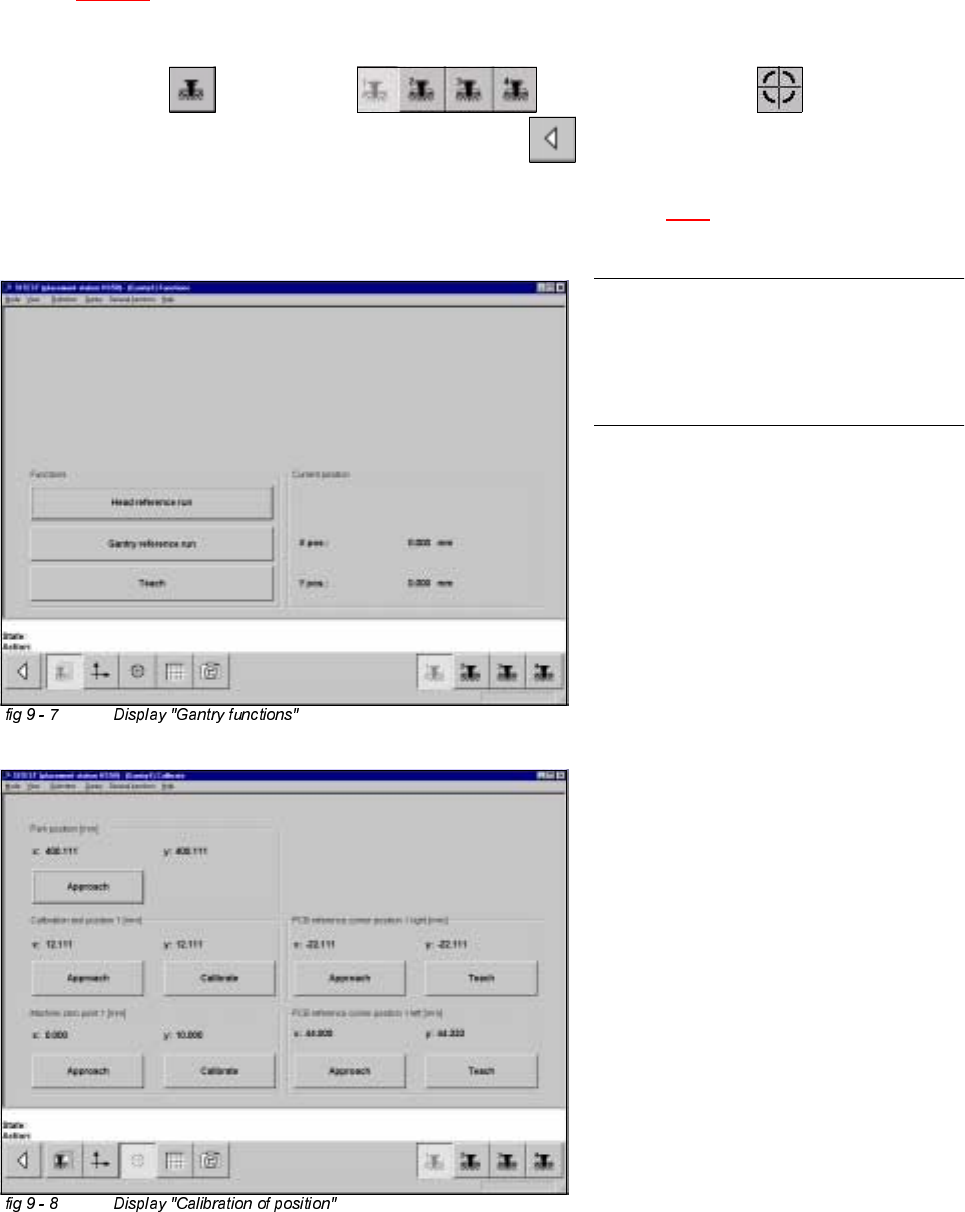
&DOLEUDWLRQRI&DOLEUDWLRQ3RVLWLRQ
Example: Placement area 1.
Å Insert the calibration tool in to the "calibration bag 1" in placement area 1.
(See
fig 9 - 1).
6,7(67
Å Select "Gantry" ==> "Gantry 1" ==> "Calibrate position" ==>
"Calibrate (field "calibration position 1")"==> "Main view" ==> "Save machine data".
Å Proceed under section "Calibration of the Pick-Up Height". (See section 9.6.3).
NOTE
Proceed the same way with gantry 2, in
order to determine the calibration position
in placement area 2.