HS50的结构及原理.pdf - 第170页
170 9 Calibration of SIPLACE HS-50 (incl. SITEST version 501.xx) Adjustment Instructions HS-50 9.5 Calibration of Calibration Position Software-Version 5.01 Edition 05/00 &DOLEUDWLRQR I&DOLEUDWLRQ3R VL…
Adjustment Instructions HS-50 9 Calibration of SIPLACE HS-50 (incl. SITEST version 501.xx)
Software-Version 5.01 Edition 05/00 9.4 Calibration of Machine Zero Point
169
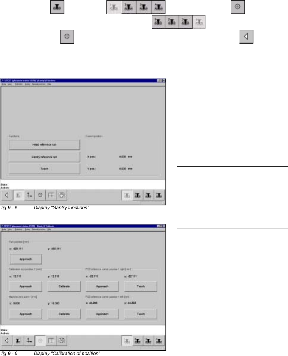
&DOLEUDWLRQRI0DFKLQH=HUR3RLQW
Example: Placement area 1.
6,7(67
Å Select "Gantry" ==> "Gantry 1" ==> "Calibrate position" ==>
"Calibrate (field "Machine zero point")" ==> "Gantry 4" ==>
"Calibrate position" ==> "Calibrate (field "Machine zero point 1")" ==> "Main view" ==>
"Save machine data".
NOTE
Make sure that all calibration data for the
C&P camera, the segment offset II (C&P -
PCB camera offset) and the PCB camera
have been determined.
The calibration of the machine zero point
must be performed with both gantries
each in placement area 1 or 2,
respectively.
NOTE
Proceed the same way with gantries 2 and
3, in order to determine the machine zero
point in placement area 2.
170
9 Calibration of SIPLACE HS-50 (incl. SITEST version 501.xx) Adjustment Instructions HS-50
9.5 Calibration of Calibration Position Software-Version 5.01 Edition 05/00
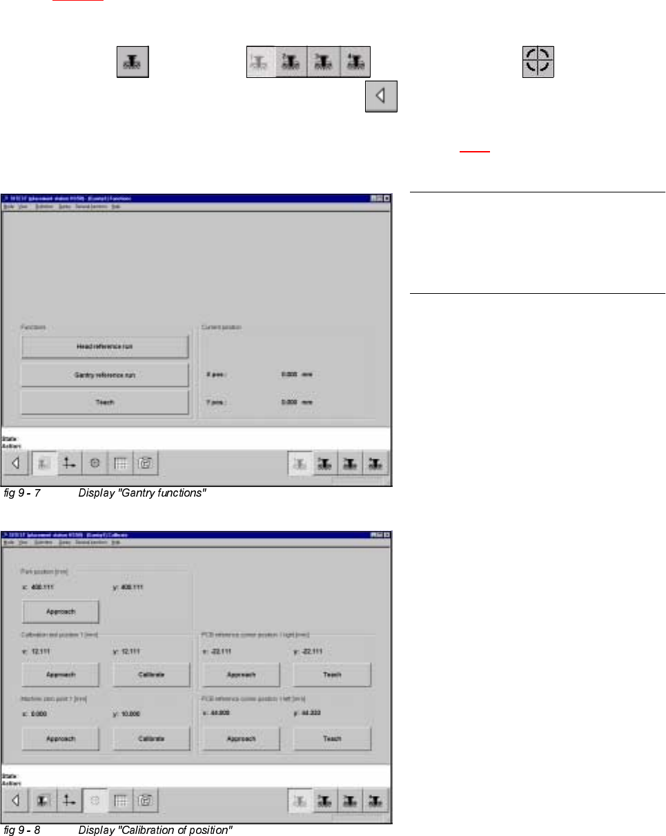
&DOLEUDWLRQRI&DOLEUDWLRQ3RVLWLRQ
Example: Placement area 1.
Å Insert the calibration tool in to the "calibration bag 1" in placement area 1.
(See
fig 9 - 1).
6,7(67
Å Select "Gantry" ==> "Gantry 1" ==> "Calibrate position" ==>
"Calibrate (field "calibration position 1")"==> "Main view" ==> "Save machine data".
Å Proceed under section "Calibration of the Pick-Up Height". (See section 9.6.3).
NOTE
Proceed the same way with gantry 2, in
order to determine the calibration position
in placement area 2.
Adjustment Instructions HS-50 9 Calibration of SIPLACE HS-50 (incl. SITEST version 501.xx)
Software-Version 5.01 Edition 05/00 9.6 Calibration Collect & Place Head Nozzle Changer
171
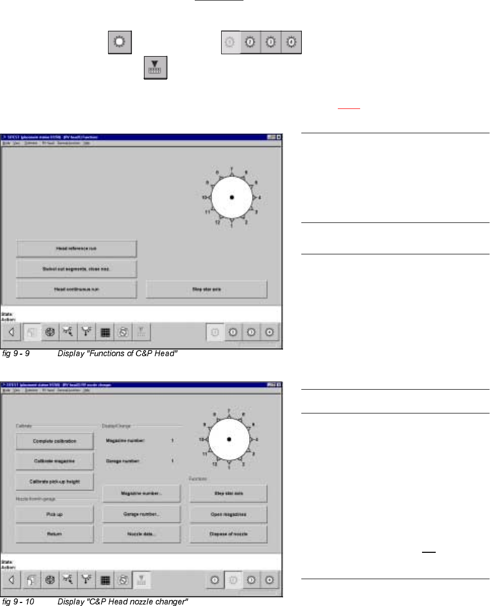
&DOLEUDWLRQ&ROOHFW3ODFH+HDG1R]]OH&KDQJHU
&RPSOHWH&DOLEUDWLRQ
Example: Nozzle changer for C&P Head 1, completely supplied with all 5 or 10 magazines.
6,7(67
Å Select "C&P Heads" ==> "C&P Head 1" ==>
"C&P Head nozzle changer" ==> "Complete calibration".
Å Proceed under section "Calibration of the Pick-Up Height". (See section 9.6.3).
NOTE
Make sure that the calibration data for the
PCB camera, the segment offset II (C&P
PCB camera offset) and the machine zero
point have been determined already.
NOTE
A nozzle changer contains 5 magazines
maximum, with 12 nozzle garages each.
For every single C&P Head, 2 nozzle
changers may be installed. During
calibration these will be handled like one
single nozzle changer with 10 maga-
zines.
NOTE
The function "Complete calibration" is
used, if the nozzle changer is completely
loaded with all 5 or 10 magazines.
All 12 nozzles must be on the C&P Head.
With the help of the function "Calibrate
current magazine", x- and y-values must
be individually determined for each
magazine if the changer is not
completely
loaded.