HS50的结构及原理.pdf - 第34页
2 Operational Safety Adjustment Instructions SIPLACE HS-50 2.2 Safety Equipment E dition 05/00 34 3RVLWLRQRI 8366W DW LR Q&RPSXWHUDQ G6RFNHW VIR U WKH&RPSRQ HQW 7 DEOH .(< (1) Sockets f…
Adjustment Instructions SIPLACE HS-50 2 Operational Safety
Edition 05/00 2.2 Safety Equipment
33
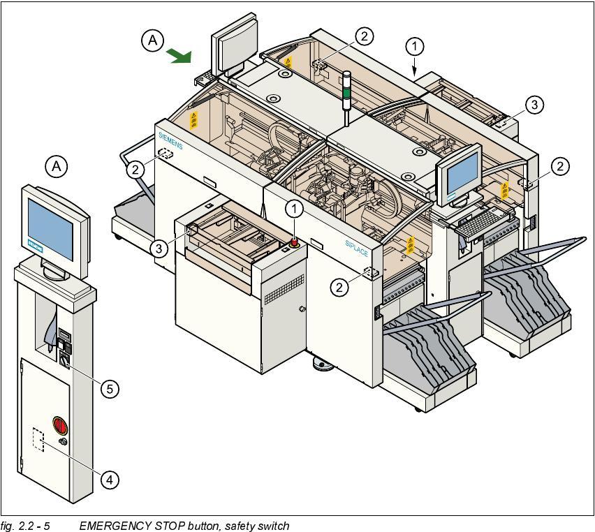
3RVLWLRQRI(0(5*(1&<6723%XWWRQV6DIHW\6ZLWFKHVHWFRQWKH3ODFHPHQW
6\ VWHP
.(<
(1) EMERGENCY STOP button
(2) Protective cover switches
(3) Protective cover switches over the PCB conveyors
(4) Protective contactor combination (PCC) in the power supply unit behind the safety doors
(5) Key switch
Key switch open position 0 for normal mode
Key switch closed position I for service purposes
2 Operational Safety Adjustment Instructions SIPLACE HS-50
2.2 Safety Equipment Edition 05/00
34
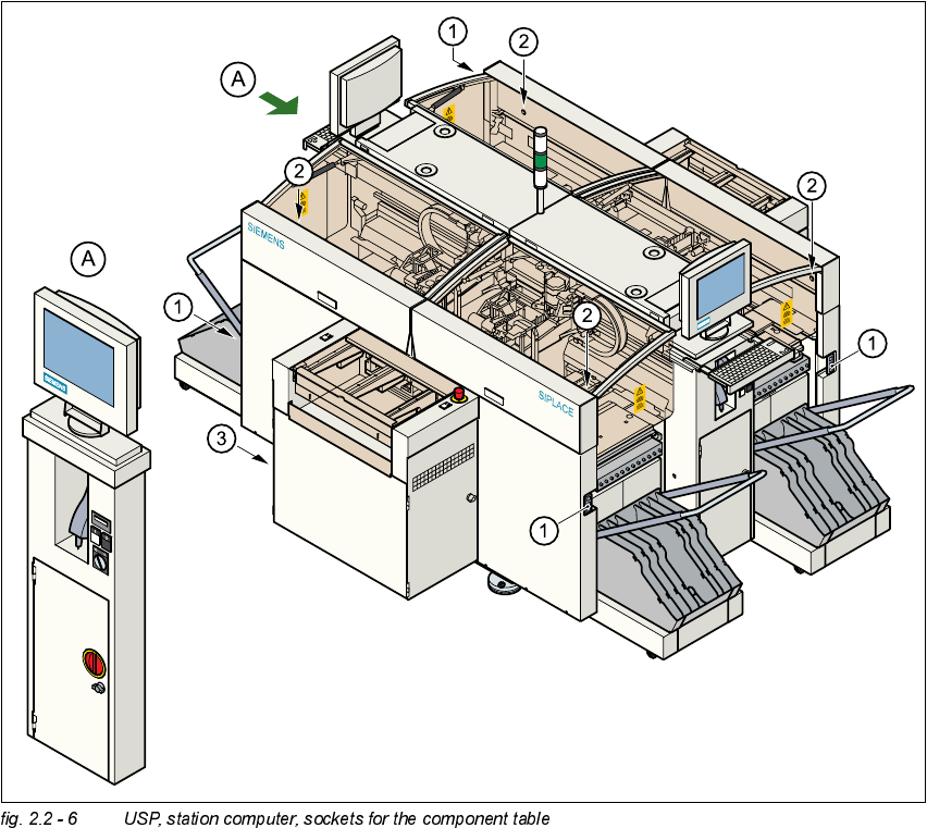
3RVLWLRQRI8366WDW LRQ&RPSXWHUDQG6RFNHWVIR UWKH&RPSRQ HQW7DEOH
.(<
(1) Sockets for component table
(2) Push button for lifting the component tables with flap open cover on top
(3) USP and station computer

Adjustment Instructions SIPLACE HS-50 2 Operational Safety
Edition 05/00 2.2 Safety Equipment
35
)XQFWLRQV
0DLQ6ZLWFKLQ2))3RVLWLRQ6H H LWHP LQILJ
The main switch disconnects the three phases L1, L2 and L3 from the power supply.
DANGER
The following components still carry potentially lethal voltages even if the main switch is switched
off:
– Cable connection terminals 1, 3 and 5 of S1 main switch
– Z1 main power filter
– BU1 service socket
– F1 automatic circuit breaker for the service socket
– The uninterruptable power supply and the station computer may also still carry potentially
lethal voltages when the main switch is switched off.
– Incorrect handling of the placement system can therefore result in death or severe injury or
considerable damage to equipment.
NOTE
The color of all individual wires, which still carry potentially lethal voltages even if the main switch
is switched off, is brown.
Å Always follow the applicable accident prevention and DIN regulations (especially DIN EN 60
204, part 1) and the specific regulations of your country.
Å The safety doors to the power supply unit must be opened by appropriately qualified and
trained personnel only.
0DLQ6ZLWFKLQ213RVLWLRQ
Switching on of the main switch, will start the station computer and machine controller.
All supply voltages, apart from the link voltages for the gantry axes (200 V) and star axes (100 V),
are then available.
(0(5*(1&<6723%XWWRQ%ODFN,WHPLQILJ
With the help of these buttons you can turn off the placement system.