HS50的结构及原理.pdf - 第50页
2 Operational Safety Adjustment Instructions SIPLACE HS-50 2.5 Energy Level after Switching Off Main Switch Edition 05/00 50 (QHUJ\ /HYHODIWHU6Z L WFK LQJ2 II0 DLQ6ZLW FK DANGER The placem ent sy stem is powere…
Adjustment Instructions SIPLACE HS-50 2 Operational Safety
Edition 05/00 2.4 Disabling of Air Supply / Discharging Pressure
49
.(<
WARNING
NEVER detach compressed air lines while they are still pressurized. Avoid the risk of injury!
(1) Shut - off valve lever in the CLOSED position
(2) Operating pressure gauge
(3) Pressure gauge for the component table operating pressure
(4) Input pressure manometer
(5) Position of the compressed air unit on the placement system behind the protective door
2 Operational Safety Adjustment Instructions SIPLACE HS-50
2.5 Energy Level after Switching Off Main Switch Edition 05/00
50
(QHUJ\/HYHODIWHU6Z L WFK LQJ2 II0DLQ6ZLW FK
DANGER
The placement system is powered with 3 x 204 VAC (USA version) 3 x 230 VAC, 3 x 380 VAC,
3 x 400 VAC respectively 3 x 415 VAC ± 5 %, 50/60 Hz mains voltage. This means that parts of
the system carry potentially lethal voltages - even when switched off at the main switch. Death,
serious injury and considerable damage may result if these placement systems are handled
incorrectly.
Å Always follow the applying accident prevention rules and DIN regulations (particularly
EN 60204, part 1).
Å The guards over the control and servo units must ONLY be opened by appropriately qualified
and trained personnel.
Adjustment Instructions SIPLACE HS-50 2 Operational Safety
Edition 05/00 2.5 Energy Level after Switching Off Main Switch
51
.(<
.(<
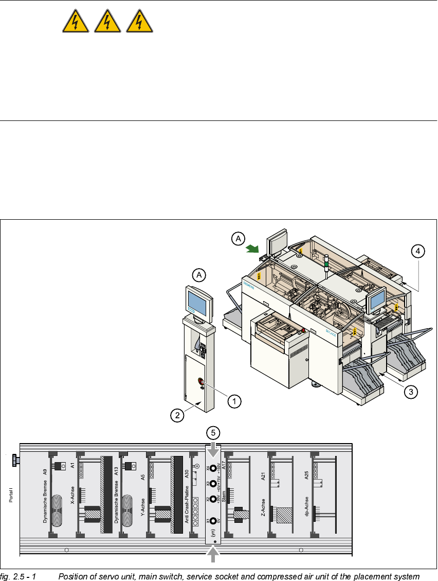
(1) Main switch
(2) Service socket behind protective door
(3) Compressed air unit
(4) Servo unit
(5) Measuring unit in servo unit
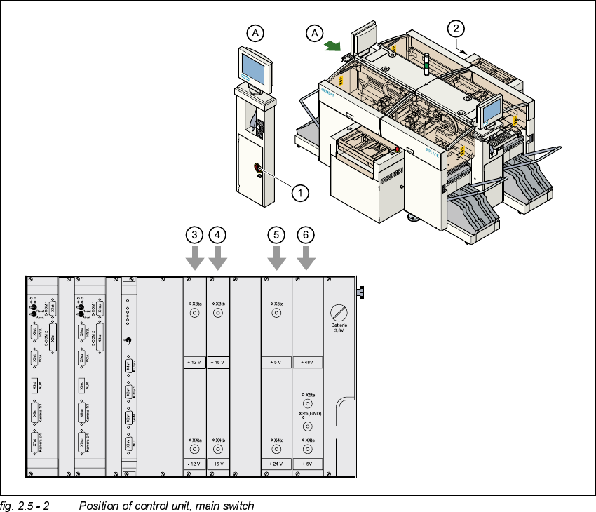
(1) Main switch
(2) Control unit
(3) Power supply unit ± 12 VDC
(4) Power supply unit ± 15 VDC
(5) Power supply unit + 5 VDC/+ 24 VDC
(6) Power supply unit + 5 VDC/+ 50 VDC