HS50的结构及原理.pdf - 第78页
4 Overview Voltages Adjustment Instructions SIPLACE HS-50 4.6 Measuring Voltages of the Power Supply Unit Edition 05/00 78 1HFHV VDU\ (TXLSPHQ WDQG7 RROV – Digital v oltmete r , class 1.5 – Measu ring ca ble wit…

Adjustment Instructions SIPLACE HS-50 4 Overview Voltages
Edition 05/00 4.6 Measuring Voltages of the Power Supply Unit
77
0HDVXULQJ9ROWDJHVRIWKH3RZHU6XSSO\ 8QLW
6DIHW\:DUQLQJV
DANGER
The placement system is powered with 3 x 204 VAC (US version) 3 x 230 VAC, 3 x 380 VAC,
3 x 400 VAC respectively 3 x 415 VAC ± 5 %, 50/60 Hz main power voltage.
– Parts of the system carry potentially lethal voltages - even when the main switch is turned off.
– Death, serious injury and considerable damage may result if these placement systems are
handled incorrectly.
Å Measurements as well as all repair work and other work must be performed by appropriately
qualified and trained personnel ONLY.
Å Please, adhere to the safety warnings in chapter 2 of this manual.
Å Please, adhere to the applicable accident prevention and DIN regulations. (Especially DIN EN
60 204, part 1).
Å Turn off the main switch and disconnect the placement system from the power supply network,
BEFORE you begin ANY repair work on it.
Å Safeguard the system against all restarts.
– If you disregard these warnings, contact with any parts carrying voltage may lead to death or
serious injury.
4 Overview Voltages Adjustment Instructions SIPLACE HS-50
4.6 Measuring Voltages of the Power Supply Unit Edition 05/00
78
1HFHVVDU\(TXLSPHQWDQG7RROV
– Digital voltmeter, class 1.5
– Measuring cable with test tip and test clampings
– Detailed circuit diagram HS-50, item number 00191281-01
– Head screw driver DIN 911, size 6
– Two - way key, 3 mm, DIN 43668 - J33, item no 00304191-01
0HDVXUHPHQW3UHSDUDWLRQRI3RZHU6XSSO\8QLW
The power supply unit and the main switch are located in the placement system frame. There is
a protective door in front of the unit, which can be opened with a two - way key.
The unit is locked in in the placement system frame with a M8 - head screw.
Taking measurements at the power supply follow these instructions:
Å Turn off the machine at the main switch.
Å Loosen the M8 - safety screw on the rear side.
Å Pull out the unit to the limit stop.
WARNING
Make sure that the power cable and the supply line of the placement system are not clamped or
damaged in their isolation.
Å Turn off the system at the main switch and start the placement system.
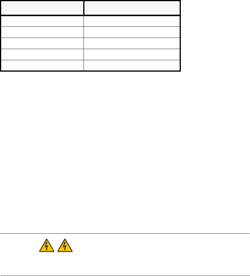
0HDVXULQJDUHD
Alternating voltage 750 V
Alternating voltage 40 A
Constant voltage 300 V
Constant voltage 30 A
Resistance 200 Ohm - 20 MOhm

Adjustment Instructions SIPLACE HS-50 4 Overview Voltages
Edition 05/00 4.6 Measuring Voltages of the Power Supply Unit
79
0HDVXULQJ9ROWDJHVRQWKH)URQW6LGHRI WKH3 RZHU6XSSO\ 8QLW
NOTE
Measurements can be taken only while the system is running. This means that the protective
covers as well as the component flaps are closed and the component tables are docked on. The
EMERGENCY STOP button is unlocked and the START button has been pressed.
Operational voltages for the servo amplifier, the lifting tables e.g. would otherwise remain
unswitched.
Module inputs are marked with odd numbers, model outputs with even numbers.
Inputs of fuses (F1 etc.) are always on the bottom side of the module, contactors (SZ1 etc.) and
inputs of motor protective switches (MS1 ...) are always on the top.