HS50的结构及原理.pdf - 第79页
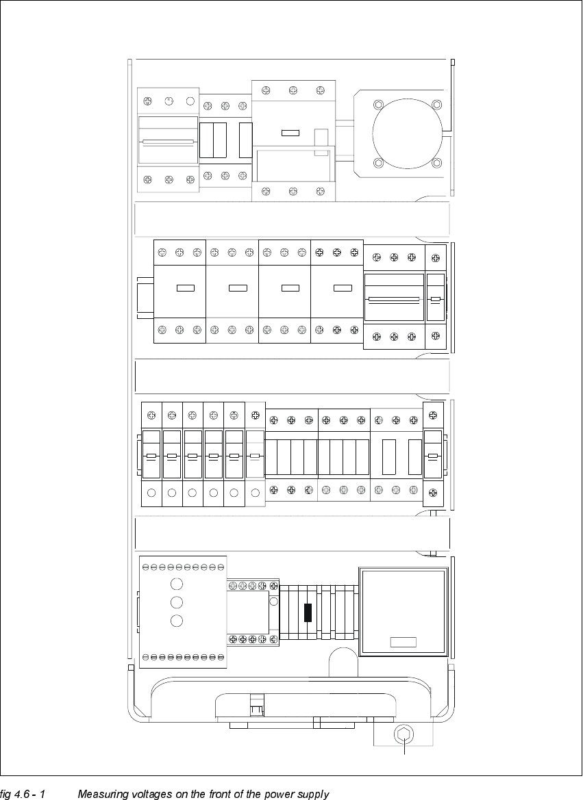
Adjustment Instructions SIPLACE HS -50 4 Overview Voltages Edition 05/00 4.6 Measuring Voltages of the P ower Supply Unit 79 0HDVXULQJ9 ROWDJHVRQWKH)URQW6LGHRI WKH3 RZHU6XSSO\ 8QLW NOTE Measure ments can …
4 Overview Voltages Adjustment Instructions SIPLACE HS-50
4.6 Measuring Voltages of the Power Supply Unit Edition 05/00
78
1HFHVVDU\(TXLSPHQWDQG7RROV
– Digital voltmeter, class 1.5
– Measuring cable with test tip and test clampings
– Detailed circuit diagram HS-50, item number 00191281-01
– Head screw driver DIN 911, size 6
– Two - way key, 3 mm, DIN 43668 - J33, item no 00304191-01
0HDVXUHPHQW3UHSDUDWLRQRI3RZHU6XSSO\8QLW
The power supply unit and the main switch are located in the placement system frame. There is
a protective door in front of the unit, which can be opened with a two - way key.
The unit is locked in in the placement system frame with a M8 - head screw.
Taking measurements at the power supply follow these instructions:
Å Turn off the machine at the main switch.
Å Loosen the M8 - safety screw on the rear side.
Å Pull out the unit to the limit stop.
WARNING
Make sure that the power cable and the supply line of the placement system are not clamped or
damaged in their isolation.
Å Turn off the system at the main switch and start the placement system.
0HDVXULQJDUHD
Alternating voltage 750 V
Alternating voltage 40 A
Constant voltage 300 V
Constant voltage 30 A
Resistance 200 Ohm - 20 MOhm

Adjustment Instructions SIPLACE HS-50 4 Overview Voltages
Edition 05/00 4.6 Measuring Voltages of the Power Supply Unit
79
0HDVXULQJ9ROWDJHVRQWKH)URQW6LGHRI WKH3 RZHU6XSSO\ 8QLW
NOTE
Measurements can be taken only while the system is running. This means that the protective
covers as well as the component flaps are closed and the component tables are docked on. The
EMERGENCY STOP button is unlocked and the START button has been pressed.
Operational voltages for the servo amplifier, the lifting tables e.g. would otherwise remain
unswitched.
Module inputs are marked with odd numbers, model outputs with even numbers.
Inputs of fuses (F1 etc.) are always on the bottom side of the module, contactors (SZ1 etc.) and
inputs of motor protective switches (MS1 ...) are always on the top.
4 Overview Voltages Adjustment Instructions SIPLACE HS-50
4.6 Measuring Voltages of the Power Supply Unit Edition 05/00
80
246
135
F3
135
246
SZ1
K14
K12
K11
135
246
MS1A
MS1
S1
MS5 MS6MS4MS3
135
2 64 2 64
1 53 31 5
42 6 624
513
F4
426
3
1
5
F10F9F8F7F6F5
111111
222 222
F1
2
1
SZ2 SZ3 SZ23
246
1351
3
5
2
4
6
2
4
6
1
3
5
K232
K234
K34
K33
K32
K31
K21
K22
K23
K24
SSK
1 375
4268
A1+
A2-
SZ4
X1
VUWW
PE
PE
N
BU1
M8
F11
2
1
54 6614 24 4434X4 X6L-
13L+ X3X1 X5 533323 43 65
Netz
Power
Channel 1
Kanal 1
Channel 2
Kanal 2