HS50的结构及原理.pdf - 第87页
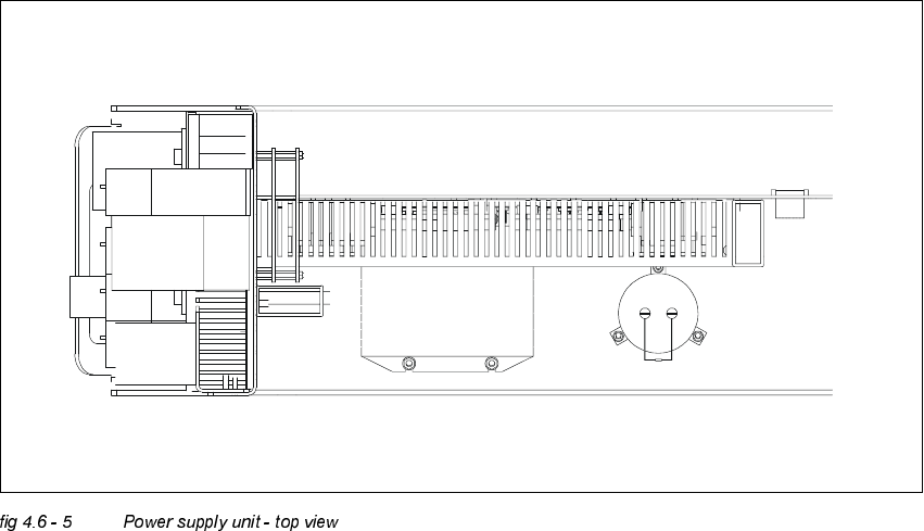
Adjustment Instructions SIPLACE HS -50 4 Overview Voltages Edition 05/00 4.6 Measuring Voltages of the P ower Supply Unit 87 &RQQHFWRU3OXJ3DQHORI3RZHU6XSSO\ 8QLW .(< 0R G XO H &RQQHFWLQJF ODPS…
4 Overview Voltages Adjustment Instructions SIPLACE HS-50
4.6 Measuring Voltages of the Power Supply Unit Edition 05/00
86
The transformer T1 generates the following voltages on the secondary:
– 3 x 140 VAC
–3 x 5 VAC
–3 x 24 VAC
–3 x 30 VAC
–3 x 6 VAC
–3 x 40 VAC
–3 x 24 VAC
0HDVXULQJ9ROWDJHVRQWKH0DLQV)LOWHU=DQG(OHFWURO\W&DSDFLWRU&
.(<
Z1 Mains filter for three - phase systems 36 A
E Input connecting terminal of the net filter Z1
A Output connecting terminal of net filter Z1
C1 Electrolyt capacitor 33000 µF / 63 V
R1 Discharging resistor
R1
C1
Z1
+
-
L1
L2
PE
L3
AE
PE
L3
L2
L1
Adjustment Instructions SIPLACE HS-50 4 Overview Voltages
Edition 05/00 4.6 Measuring Voltages of the Power Supply Unit
87
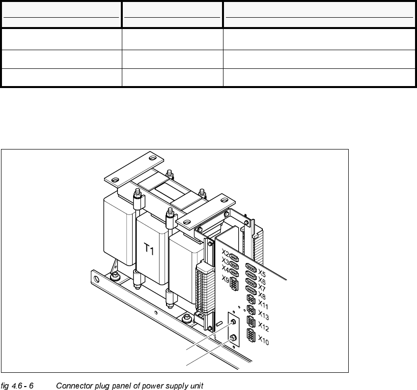
&RQQHFWRU3OXJ3DQHORI3RZHU6XSSO\ 8QLW
.(<
0RGXOH &RQQHFWLQJFODPSV 9ROWDJHV
Mains filter L1, L2, L3 3 x 204 VAC / 3 x 380 VAC
3 x 400 VAC / 3 x 415 VAC
Electrolyt capacitor C1 + / - 50 VDC
T1 Rotary current transformer, 11,1 kVA
P200 V Screw connection M6 (+) for the supply of the servo amplifier of the x /y - axes
N200 V Screw connection M8 (-) for the supply of the servo amplifiers of the x /y - axes
X2 to PC
X3 to monitor 1
X4 to monitor 2
X5 to lifting table 1, PCB conveyor 1
X6 to lifting table 2, PCB conveyor 1
X7 to lifting table 3, PCB conveyor 2 (option)
X8 to lifting table 4, PCB conveyor 2 (option)
X9 to servo unit
X10 to main distributor (unsaturated DC voltages)
X11 to PCB handling / to lifting table control
X12 from / to main distributor, (control signals, power supply)
X13 from / to main distributor, (PCC - peripheral unit)
P 200 VDC
N 200 VDC

4 Overview Voltages Adjustment Instructions SIPLACE HS-50
4.6 Measuring Voltages of the Power Supply Unit Edition 05/00
88
NOTE
Pin configuration of single connectors can be checked in the detailed circuit diagram, section 3.