HS50的结构及原理.pdf - 第97页
Adjustment Instructions SIPLACE HS -50 5 Single and Dual PCB Conveyor Edition 05/00 5.6 Limit Switch and Pr oximity Switch Width Adjustment 97 /LPLW6Z LWFKDQ G3UR[LPLW\ 6ZLWF K :LG WK$ GMXV W PHQW Å Positi…

5 Single and Dual PCB Conveyor Adjustment Instructions SIPLACE HS-50
5.5 Adjustment of Transport Parallelism Edition 05/00
96
NOTE
Due to limited accessibility, adjustments as described above can only be performed from one side
each.
Å Move the conveyor to 100 mm on one side.
Å Loosen the three screws and take out the disk of the pressure flange.
NOTE
Watch out for the annular spring; it might fall.
Å Hold on to the untightened spindle.
Å With the help of the spindle, move the conveyor on the opposite side, until you reach a distance
of 100 mm there as well.
Å Check, if the measures of the conveyor are by now identical on both sides.
Å In order to fix the spindle follow the same procedure, just the opposite way.
NOTE
Make sure that during the fixing of the spindle, the conveyor remains unmoved.
6,7(67
Å Use the conveyor functions, in order to test the conveyor width adjustment, .
Adjustment Instructions SIPLACE HS-50 5 Single and Dual PCB Conveyor
Edition 05/00 5.6 Limit Switch and Proximity Switch Width Adjustment
97
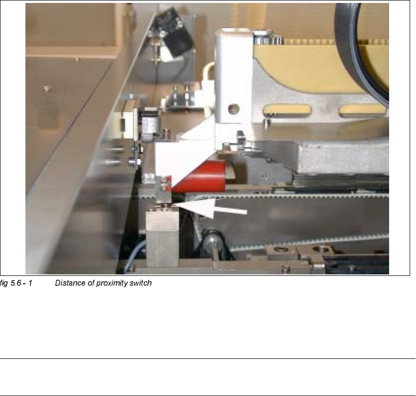
/LPLW6ZLWFKDQG3UR[LPLW\ 6ZLWFK:LGWK$GMXV W
PHQW
Å Position gantry 2 above the proximity switch.
Å Set a distance of 0.4 mm.
NOTE
Adjust the second conveyor the same way.
5 Single and Dual PCB Conveyor Adjustment Instructions SIPLACE HS-50
5.6 Limit Switch and Proximity Switch Width Adjustment Edition 05/00
98