00196614-03_AI_Vakuumpumpe_SXDX12_de_en.pdf - 第107页
Fitting the Vacuum Pump 3.3.7 Connecting the Vacuum Hoses Preparatory Steps Vacuum Pump Vakuumpumpe 107 3.3.7 3 . 3 . 7 C o n n e c t in g t h e V a c u u m H o s e s Connecting the Vacuum Hoses Original state of compres…
Fitting the Vacuum Pump
Preparatory Steps 3.3.6 Access to the Trailing Cable Hoses
106 Vacuum Pump Vakuumpumpe
3.3.5.1
3.3.5.1 Reversing the Direction of Pump Operation
Reversing the Direction of Pump Operation
3.3.6
3.3.6 Access to the Trailing Cable Hoses
Access to the Trailing Cable Hoses
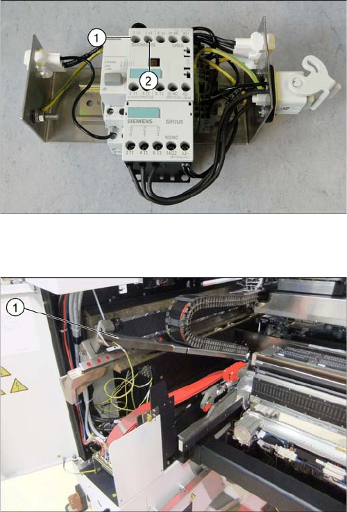
► On the connection unit, exchange the connections L1
(1) and L2 (2), to reverse the direction of pump oper-
ation.
► Check the direction of pump operation again (see
"3.3.5 Checking the Direction of Pump Operation"
[ ➙ 105]).
► In order to access the outlet of the C&P20 A head
trailing cable, you may need to remove the table
height adjustment and the calibration tool holder.
► If necessary, open the cover on the cable duct and lift
it up during the conversion work (1).
Fitting the Vacuum Pump
3.3.7 Connecting the Vacuum Hoses Preparatory Steps
Vacuum Pump Vakuumpumpe 107
3.3.7
3.3.7 Connecting the Vacuum Hoses
Connecting the Vacuum Hoses
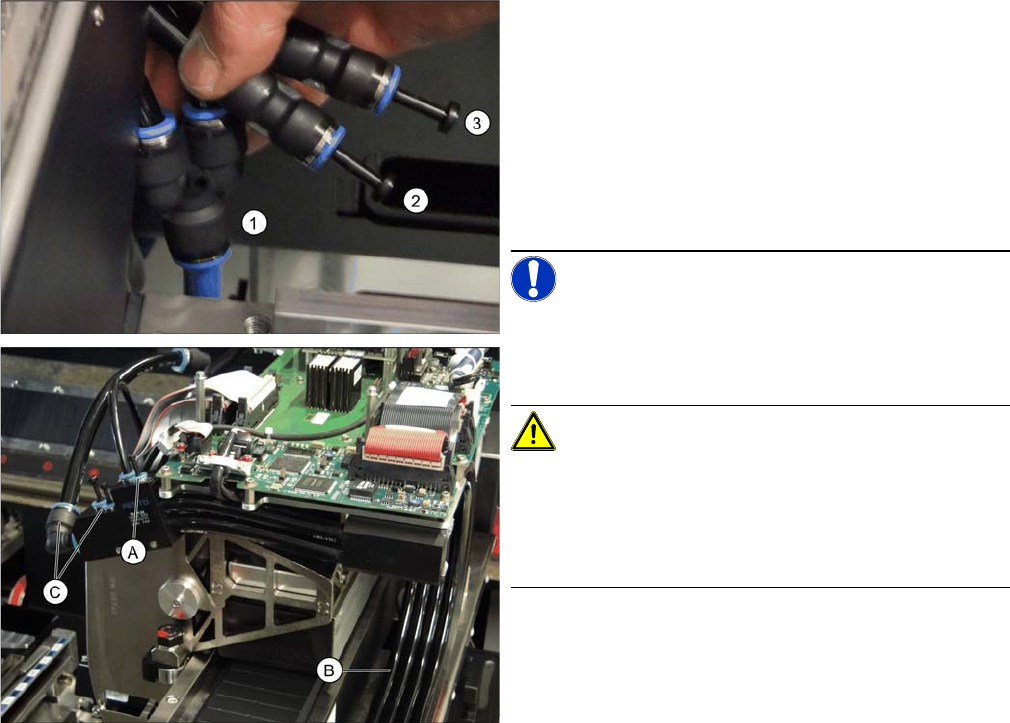
Original state of compressed air operation and target state for vacuum operation
In compressed air operation, compressed air is present at all connections of the distributor (A and C)
and the trailing cable hoses.
In vacuum operation, one connection (A) on the distributor still has compressed air while three connec-
tions (C) are used for the vacuum.
This means that, after conversion, the inner hose (B) of the trailing cable is still operated with com-
pressed air while the three outer ones must be run with vacuum.
Conversion to vacuum operation
A = compressed air connection on head
B = compressed air hose
C = vacuum connections on head
In the original state, two active compressed air lines run
from the C&P20A head, via a Y coupling to a PUN 12
hose (1) which is connected to the compressed air unit.
The two vacuum lines are inactive in the original state
and are sealed with dummy plugs (2 and 3).
► Unplug the Y coupling (1). Insert a PUN 10/12 cou-
pling between the blue compressed air hose for the
pneumatic supply and the supply hose for the pres-
sure control valve [03053793-xx].
NOTICE!
The compressed air hose for the pressure control valve is
the top one on the distributor unit (A), running inside, next
to the vacuum hoses (B).
CAUTION!
Make sure to check that you have connected the correct
compressed air hose from the trailing cable to the pres-
sure control valve. If not, the vacuum hoses on the DP
drive of the C&P20 A or on the segments of the C&P12
(DLM) could be damaged.
► Remove the two dummy plugs (2) and (3).
Fitting the Vacuum Pump
Preparatory Steps 3.3.7 Connecting the Vacuum Hoses
108 Vacuum Pump Vakuumpumpe
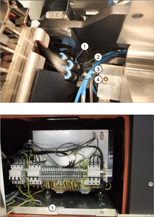
► Connect the relevant vacuum hose to each free
connection (2) to (4).
▪ Use the 1 m hoses for gantry 1. (3x [03090005-xx])
▪ Use the 2 m hoses for gantry 2. (3x [03090006-xx])
► On machines with serial number Kxxx/Lxxx/Mxxx, at
gantry 2, run the hoses around the transformer (1) to
the other side (to the pump installation location). Ma-
chines with serial number Nxxx are no longer
equipped with a transformer at this location.