00196614-03_AI_Vakuumpumpe_SXDX12_de_en.pdf - 第94页
Fitting the Vacuum Pump Preparatory Steps 3.3.2 Prefitting the Vacuum Pump 94 Vacuum Pump Vakuumpumpe 3.3.2.3 3 . 3 . 2 . 3 A d ju s t in g t h e S u p p ly V o lt a g e o f t h e V a c u u m P u m p ( F r o m M a c h in…
Fitting the Vacuum Pump
3.3.2 Prefitting the Vacuum Pump Preparatory Steps
Vacuum Pump Vakuumpumpe 93
3.3.2.2
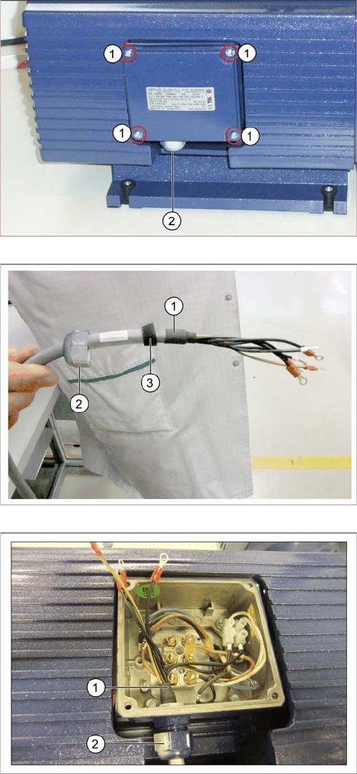
3.3.2.2 Connecting the Power cable
Connecting the Power cable
1. 4 screws on the cover
2. Tension relief
► Remove the four screws (1) fastening the cover on
the electricity connection box and then remove the
cover.
► Turn the strain relief out (2).
1. Power cable
2. Tension relief
► Thread the power cable [03079997-xx] (1) through
the strain relief (2) and the sealing ring (3).
1. Power cable
2. Tension relief
► Thread the power cable into the electricity connection
box (1) and turn the strain relief until tight (2).
Fitting the Vacuum Pump
Preparatory Steps 3.3.2 Prefitting the Vacuum Pump
94 Vacuum Pump Vakuumpumpe
3.3.2.3
3.3.2.3 Adjusting the Supply Voltage of the Vacuum Pump (From Machine No. N001)
Adjusting the Supply Voltage of the Vacuum Pump (From Machine No. N001)
► Depending on the input voltage to the power supply, adjust the vacuum pump to the same input volt-
age and power supply. Connector X96 supplies the vacuum pump with the three phases L1, L2, and
L3 required; for that reason, the relevant country-specific input voltage is applied (see also the doc-
umentation of the rotary field [03125519-xx]). The corresponding label is located on the power supply
unit at connector X101.
► When installing the vacuum pump, make sure that the 110V transformer option is installed and that
the input voltage is 110V.
► Connector X96 is supplied by the 110V transformer (US option). For this reason, set the input voltage
of the vacuum pump to this value.
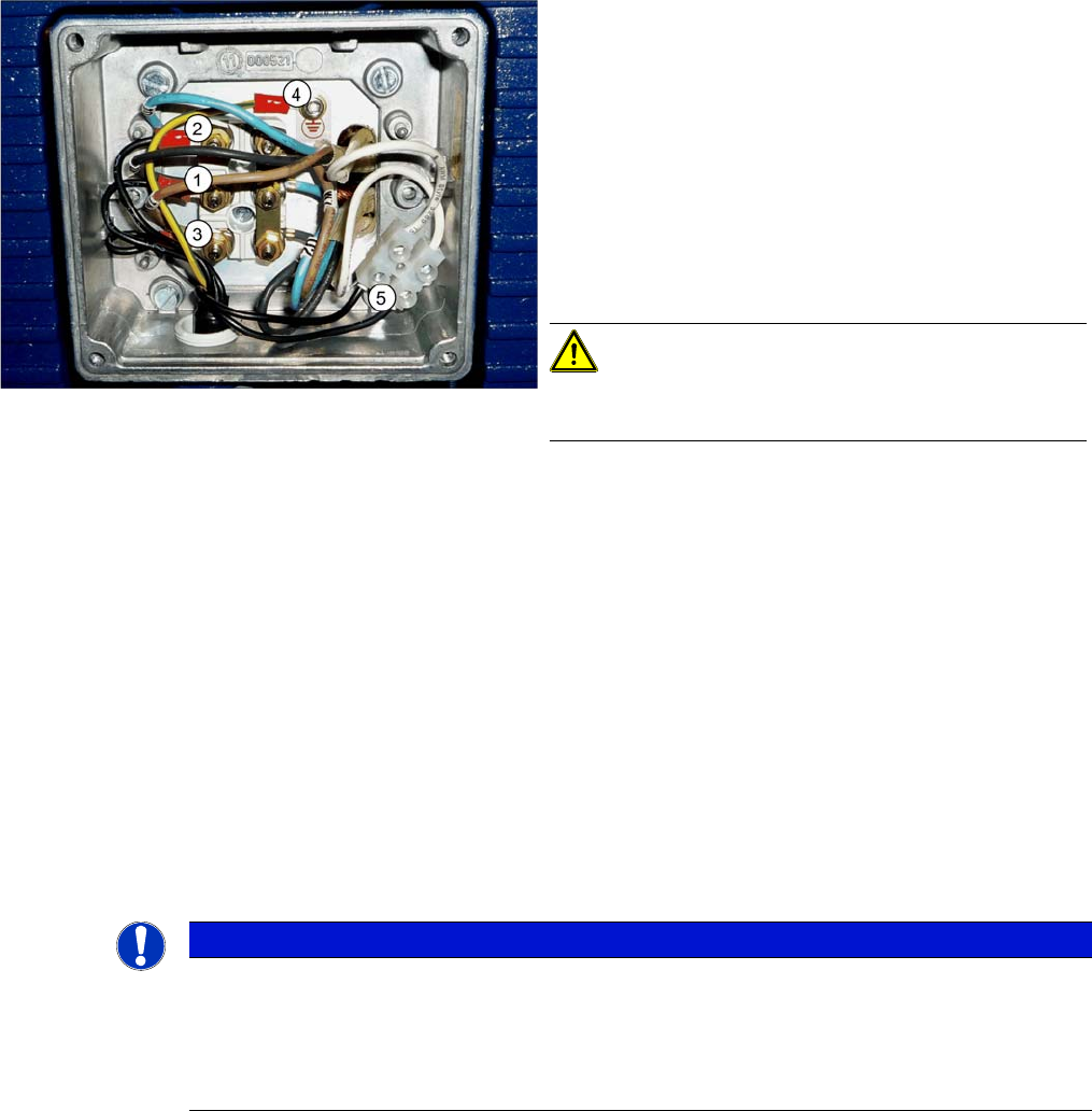
► Disconnect the vacuum pump power cable [03079997-xx].
▪ Conductor (1) to connection U1
▪ Conductor (2) to connection V1
▪ Conductor (3) to connection W1
► Do not disconnect the protective conductor and the temperature monitoring.
► Fit the cable connections to the pump connections as
follows:
⇨ Conductor (1) to connection U1
⇨ Conductor (2) to connection V1
⇨ Conductor (3) to connection W1
⇨ Protective ground 4 – to connection 4
⇨ The two black cables (temperature monitor) are
connected to a luster terminal (5).
► Remove the nuts from the connections U1, V1, W1
and the protective ground connection (4).
CAUTION!
Make sure that none of the nuts or washers fall inside the
pump.
► Place a washer onto each connection. Position the
corresponding cable shoe onto each connection.
Place another washer onto each cable shoe.
► Hand-tighten the nuts.
NOTICE
Machines with serial nos.: Kxxx/Lxxx/Mxxx
On machines with serial numbers Kxxx/Lxxx/Mxxx, the vacuum pump must be operated in a
delta connection. The power supply transformer of the machine supplies the voltage.
From serial number N001, the vacuum pump is connected directly to the supply mains at the
customer's site via the main switch of the machine.
Fitting the Vacuum Pump
3.3.2 Prefitting the Vacuum Pump Preparatory Steps
Vacuum Pump Vakuumpumpe 95
► Place the cover back on the electricity connection box and fix it with the four screws which you re-
moved.
3.3.2.4
3.3.2.4 Fitting and Positioning the Filter
Fitting and Positioning the Filter
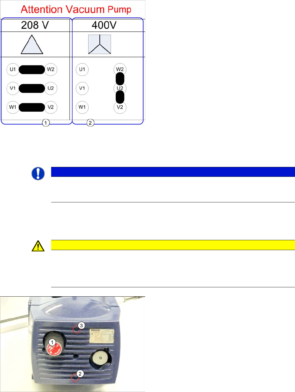
Input voltage of the vacuum pump
1. Input voltage 208V -> operation with 110V transform-
er (US option) (jumper [03110977-xx] removed)
► Wire the motor terminal block according the adjoining
graphic 208.
► Use the plates to connect
▪ U1 with W1
▪ V1 with U2
▪ W1 with V2
1. Input voltage 400V -> operation with 3x208V (jumper
03110977-01 installed)
► Wire the motor terminal block according the adjoining
graphic 400.
► Use the plates to connect W2 with U2 with V2 (use
two plates between W2 and U2).
► After that, re-connect the cable power supply vacuum
pump [03079997-xx]
▪ Conductor (1) to connection U1
▪ Conductor (2) to connection V1
▪ Conductor (3) to connection W1
NOTICE
Input voltage at conversion
When converting to the 110V transformer US option, the input voltage at the vacuum pump
needs to be re-connected according to the information.
CAUTION
Do not lift on the front plate
The front plate of the vacuum pump is only fixed with rubber buffers.
► Take care not to damage the rubber buffers.
► Always lift the vacuum pump on its housing or filter, not on the front plate.
1. Leakage valve
2. Fastening screw
3. Fastening screw
► Unscrew the leakage valve.
► Remove the screws (2 and 3) fastening the front plate
and then remove the front plate.