00196614-03_AI_Vakuumpumpe_SXDX12_de_en.pdf - 第96页
Fitting the Vacuum Pump Preparatory Steps 3.3.2 Prefitting the Vacuum Pump 96 Vacuum Pump Vakuumpumpe 1. Fitting G1 - G3/4 [03088251-xx] ► Apply Loctite 55 to the threaded connection and screw in the fitting ins tead of …
Fitting the Vacuum Pump
3.3.2 Prefitting the Vacuum Pump Preparatory Steps
Vacuum Pump Vakuumpumpe 95
► Place the cover back on the electricity connection box and fix it with the four screws which you re-
moved.
3.3.2.4
3.3.2.4 Fitting and Positioning the Filter
Fitting and Positioning the Filter
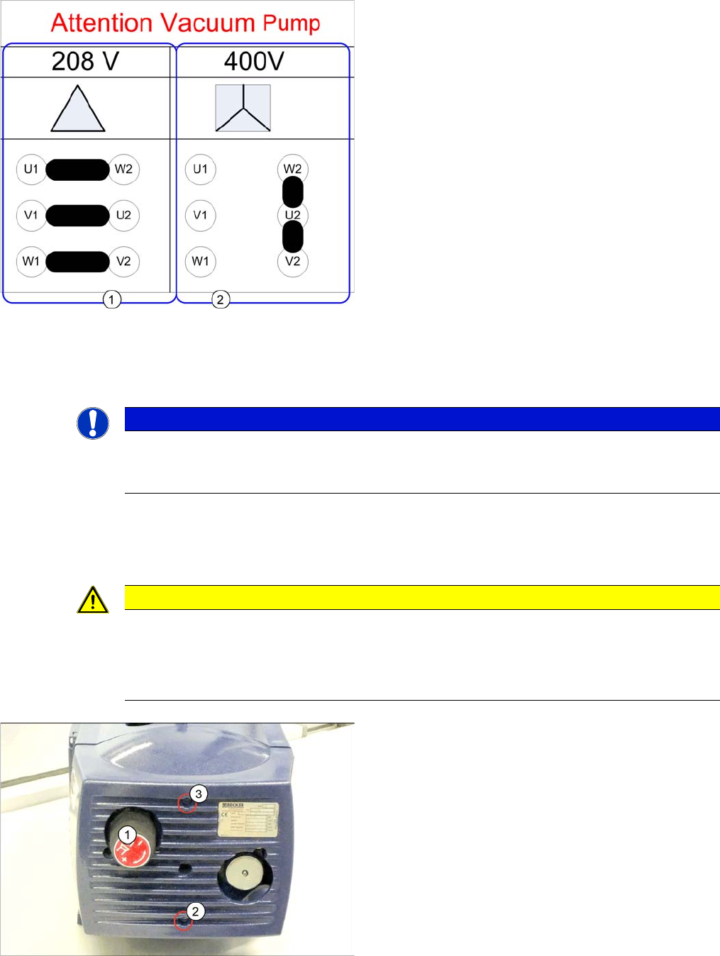
Input voltage of the vacuum pump
1. Input voltage 208V -> operation with 110V transform-
er (US option) (jumper [03110977-xx] removed)
► Wire the motor terminal block according the adjoining
graphic 208.
► Use the plates to connect
▪ U1 with W1
▪ V1 with U2
▪ W1 with V2
1. Input voltage 400V -> operation with 3x208V (jumper
03110977-01 installed)
► Wire the motor terminal block according the adjoining
graphic 400.
► Use the plates to connect W2 with U2 with V2 (use
two plates between W2 and U2).
► After that, re-connect the cable power supply vacuum
pump [03079997-xx]
▪ Conductor (1) to connection U1
▪ Conductor (2) to connection V1
▪ Conductor (3) to connection W1
NOTICE
Input voltage at conversion
When converting to the 110V transformer US option, the input voltage at the vacuum pump
needs to be re-connected according to the information.
CAUTION
Do not lift on the front plate
The front plate of the vacuum pump is only fixed with rubber buffers.
► Take care not to damage the rubber buffers.
► Always lift the vacuum pump on its housing or filter, not on the front plate.
1. Leakage valve
2. Fastening screw
3. Fastening screw
► Unscrew the leakage valve.
► Remove the screws (2 and 3) fastening the front plate
and then remove the front plate.
Fitting the Vacuum Pump
Preparatory Steps 3.3.2 Prefitting the Vacuum Pump
96 Vacuum Pump Vakuumpumpe
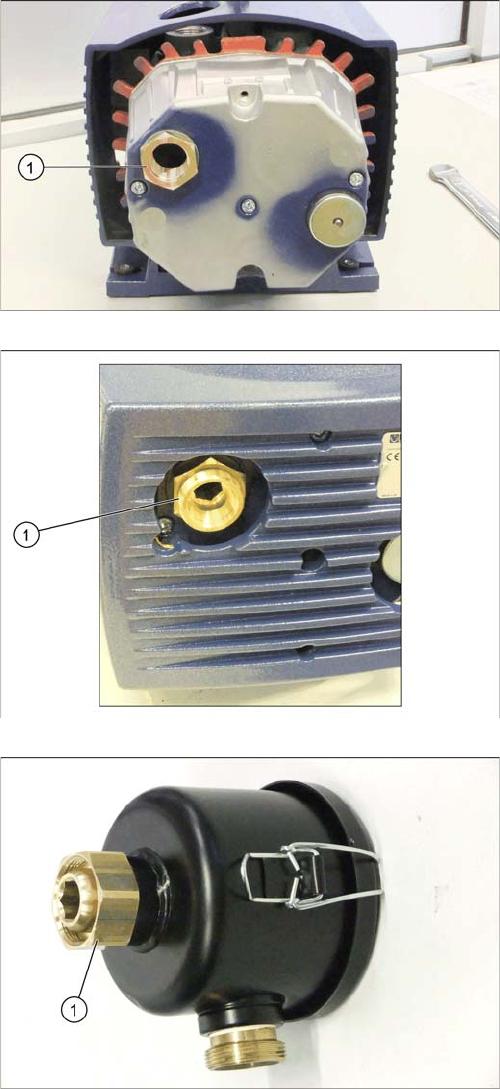
1. Fitting G1 - G3/4 [03088251-xx]
► Apply Loctite 55 to the threaded connection and
screw in the fitting instead of the leakage valve (1).
Observe the installation instructions from the pump
manufacturer. The thread sealing cord must be
wound on in the direction of the thread.
► Replace the cover and fix it with the two screws which
you removed.
► Screw the "double nipple, detachable G3/4 Ms"
[03038435-xx] apart and screw one half into the
fitting (1). Apply Loctite 55 to the threaded connec-
tion.
Observe the installation instructions from the pump
manufacturer. The thread sealing cord must be
wound on in the direction of the thread.
► Screw the second half of the "double nipple, detach-
able" [03038435-xx] into the filter (1). Apply Loctite
55 to the threaded connection.
Observe the installation instructions from the pump
manufacturer. The thread sealing cord must be
wound on in the direction of the thread.
Fitting the Vacuum Pump
3.3.2 Prefitting the Vacuum Pump Preparatory Steps
Vacuum Pump Vakuumpumpe 97
3.3.2.5
3.3.2.5 Preparing and Connecting the Distributor Block
Preparing and Connecting the Distributor Block
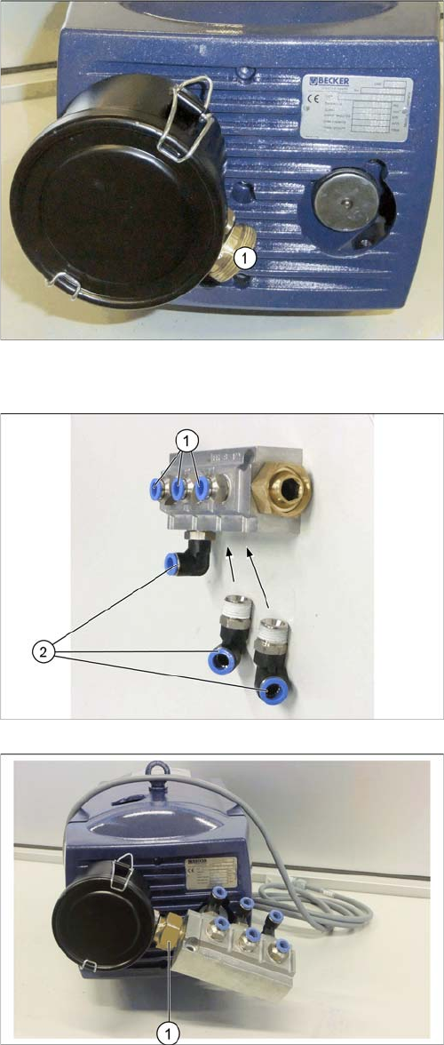
1. Four o'clock position
► Screw the filter insert [03077677-xx] onto the first half
of the double nipple and into the pump. First apply
Loctite 55 to the threaded connection.
► Correctly position the filter. The connecting piece
must point to 4 o'clock (1).
► Tighten the nuts with the "spanner wrench SW36"
[03090043-xx].
► (1) Screw a double nipple G3/4 brass [03093668-xx]
into the filter. First apply Loctite 55 to the threaded
seal.
1. 3x push-in L-fitting QS-1/2-10 [03038816-xx]
2. 3x push-in L-fitting QSL-1/2-10 [03081051-xx]
► Screw the three 10er angle connections to the distrib-
utor block [03086336-xx].
► Use the M36 open-jawed spanner [03090043-xx]
provided to fix the distributor block in the position
shown (1).