00197461-01_AI_Portaltausch_X-Serie_S_INTERN_de_en - 第62页
Installation Converting Attached Parts 62 Gantry Exchange Portaltausch 3.3 3 . 3 C o n v e r t in g A t t a c h e d P a r t s Converting Attached Parts The following parts must be atta ched as new parts or taken off the …
Installation
Removing the Gantry
Gantry Exchange Portaltausch 61
Removing the gantry
► Hold the gantry well for the following tasks.
If possible, enlist the help of a second person to press the gantry from the outside, towards the center
of the machine. This fixes the gantry into place while it is being screwed down.
► Loosen the last fastening screw. The gantry is now no longer connected to the machine.
► Carefully take the gantry out of the machine. Place it down on a suitable surface, with the side away
from the magnets underneath.
See also
4.1.1 Gantry interface [ ➙ 69]
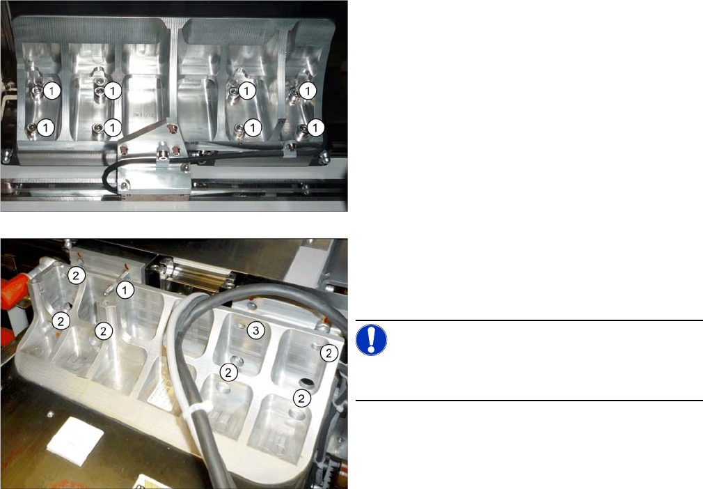
► Make sure that all connections between the gantry
and the machine have been unplugged.
► Loosen the eight screws (1) fastening the underside
of the gantry.
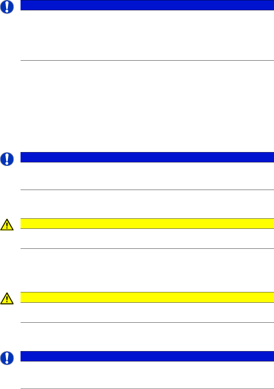
► Replace one of the top fastening screws with a
threaded bolt M6x50 (1). Rotate the threaded bolt
slightly into the thread until the end stop. This gives
the gantry additional support during removal.
NOTICE!
The threaded bolt is used later on to help fit the new gan-
try.
► Loosen the six other fastening screws (2). One fas-
tening screw remains for the moment (3). This is
enough to fix the gantry when it is inactive.
Installation
Converting Attached Parts
62 Gantry Exchange Portaltausch
3.3
3.3 Converting Attached Parts
Converting Attached Parts
The following parts must be attached as new parts or taken off the old gantry and attached to the new
one.
Fitting the scale
► Fit the scale to the gantry, and also read the section "Replacing the Scale" in the service manual for
HF/X-Series (internal version) [00195654-xx].
Incremental encoder
► Dismantle the incremental encoder from the old gantry. Read the relevant section in the service man-
ual.
Head interface and Vision Board Spread Spectrum
► Read the relevant sections in the service manual.
Temperature sensor
► Read the relevant section in the service manual.
We recommend that you fasten the corresponding cable with cable ties, after installation. Fasten it
until then with a cable tie to the gantry.
Buffer
► Dismantle the buffer and fit this to the new gantry.
NOTICE
Recommendations
We recommend that you take the attached parts off the old gantry and fit them to the new gantry
when the gantry is outside the machine.
It is helpful to place the old and new gantries next to one another and to fit a part onto the new
gantry, as soon as you have taken it off the old one. This makes it easier to clearly allocate
screws etc to the right place.
NOTICE
Do not fit the incremental to the new gantry yet.
► We recommend that you only fit the incremental encoder once you have fitted the new gan-
try in the machine.
CAUTION
Plastic covers
► Check whether the plastic covers are present on connector X1 of the head interface.
CAUTION
Heat-conductive rubber
► Take care of the heat-conductive rubber under the board.
NOTICE
Threaded rods
► If required, use two counterlocked M8 nuts, in order to loosen the threaded rods still in the
thread.

Installation
Converting Attached Parts
Gantry Exchange Portaltausch 63
Head adapter HCU with protective plate
► Read the relevant section in the service manual.
The PCB Camera
► Read the relevant section in the service manual.
Hose on the silencer
► Disconnect the hose on the silencer from the old gantry and fit it onto the new gantry.
CAUTION
Connectors, HCU
► Make sure that the head adapter board is connected to the head interface via a press-fit
connection from below.
► Do not loosen the two screws fastening the HCU.
CAUTION
Loctite 241
► Secure the screws fastening the PCB camera with Loctite 241.