00198351-01_AI_Location 2 Upgrade Kit_E by SIPLACE_en.pdf - 第9页
Assembly Instructions E by SIPLACE Location 2 Upgrade Kit 04/2017 1 Introduction 1.2 Preparatory Work... 9 1.2 Preparatory Work... Purpose and Scope Before performing any preventive maintenance work, conversion work or s…
1 Introduction
1.1 Safety Instructions
Assembly Instructions E by SIPLACE
Location 2 Upgrade Kit 04/2017
8
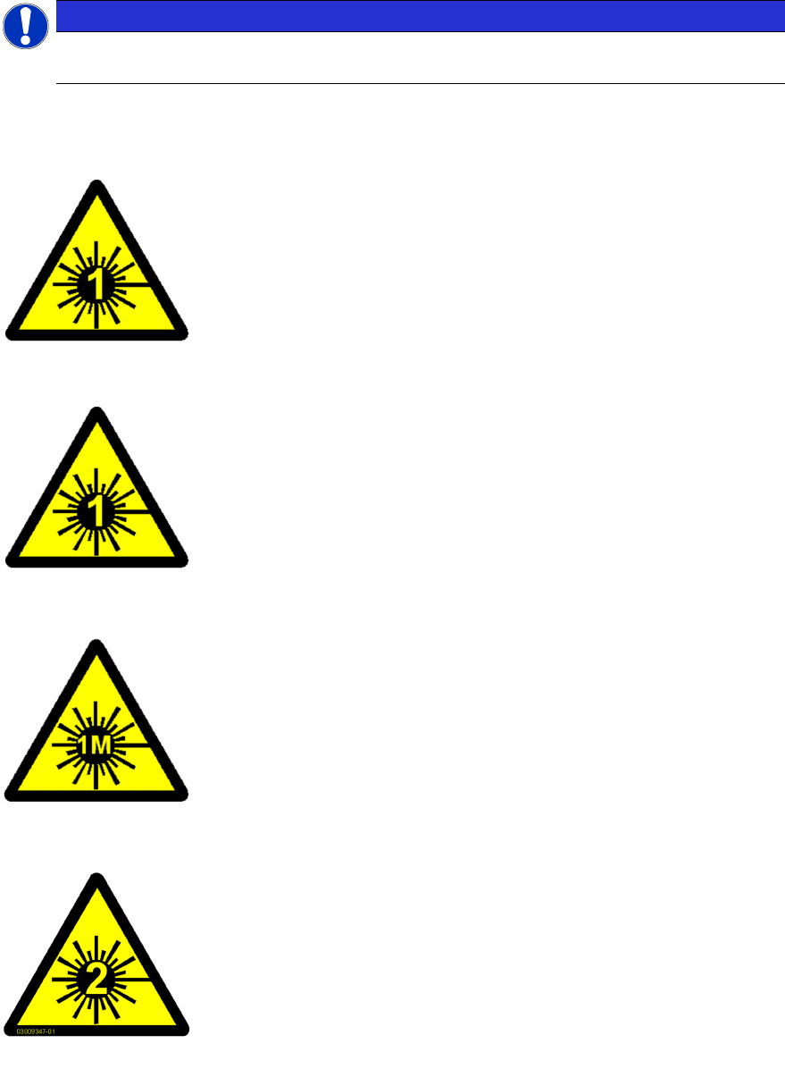
1.1.8 Laser Classification
NOTICE
Laser class 1 and 1M
Modules in laser classes 1 and 1M are not labeled.
1.1.8.1 Laser Class 1
Classification of the Whole Machine
All installed camera systems and the whole machine (when ready for
operation) are assigned to laser class 1.
The laser classes are determined according to DIN EN 60825-1:2001.
Classification of the Camera Systems
The following camera systems are assigned to laser class 1:
●
Stationary component cameras for the SIPLACE TwinStar (Twin-
Head) and the SIPLACE Multistar (CPP)
●
Component camera, stationary, P&P, type 33, 55 x 45, digital
●
Component camera, stationary, P&P, type 25, 16 x 16, digital
●
Component camera, stationary, P&P, type 36, 32 x 32, digital
1.1.8.2 Laser Class 1M
Do not look directly at this with optical instruments!
The following camera systems are assigned to laser class 1M:
●
CO camera C&P, type 23, 6 x 6 on the SpeedStar
●
CO camera C&P, type 41, 6 x 6 on the SpeedStar
●
CO camera C&P, type 30, 27 x 27 on the MultiStar
●
CO camera C&P, type 30, 18 x 18 on the 12-segment Col-
lect&Place head
1.1.8.3 Laser class 2
Laser radiation
Do not look into beam!
The following modules are assigned to laser class 2:
●
PCB barcode scanner
●
Component sensor on the SpeedStar
●
Component sensor on the MultiStar
The entire machine is classified as laser class 2 if the coplanarity laser
module option is installed.
Assembly Instructions E by SIPLACE
Location 2 Upgrade Kit 04/2017
1 Introduction
1.2 Preparatory Work...
9
1.2 Preparatory Work...
Purpose and Scope
Before performing any preventive maintenance work, conversion work or service work, a procedure
of locking and tagging must be followed and warning signs must be attached if not stated other-
wise. If it is not necessary to switch off the machine, it is explicitly mentioned.
The procedure, when followed correctly, eliminates the possibility of an employee being injured.
NOTICE
Additional safety measures
These procedures represent the minimum lock/tag out requirements for the machine during
preventive maintenance work and service work. Any additional safeguards needed to com-
plete work safely can be specified by facilities supervision, the safety officer, the safety
committee and the health department.
Description
Whenever it becomes necessary to isolate, control and release energy, the following procedure is
to be followed.
► Notify affected employees.
► Switch off the machine and all additional devices. Carry out all normal stopping procedures:
ð Press the STOP button.
ð Shut down the station computer.
ð Switch the machine off at the main switch.
► Isolate the machine from all its energy sources:
ð Shut off the compressed air supply.
ð Shut off the main power supply.
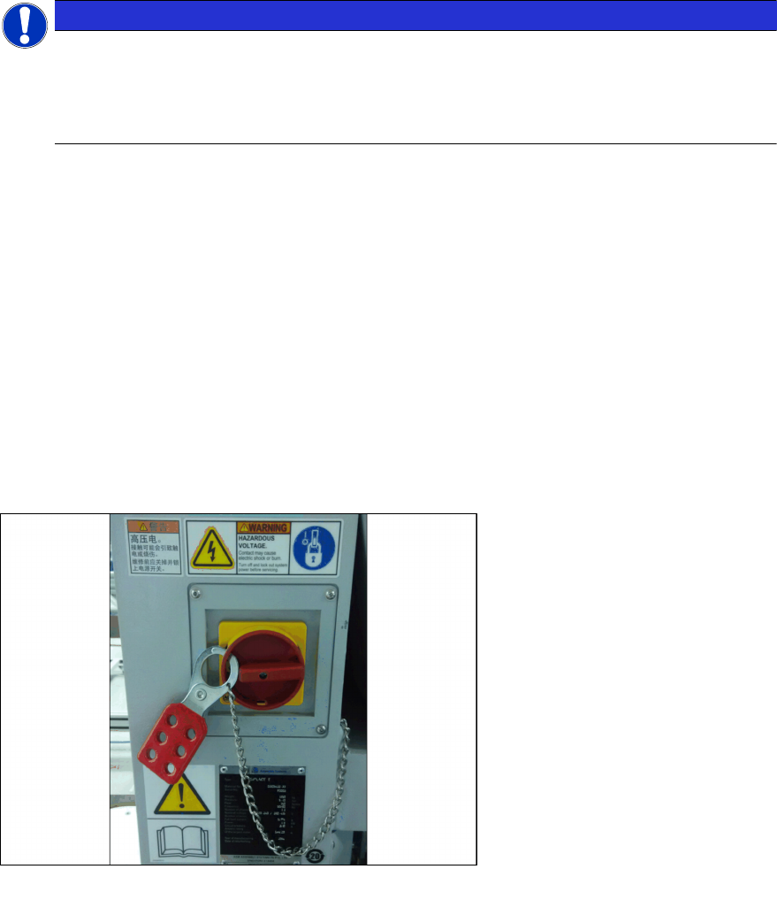
► Lock out the machine.
ð Attach a lock wherever possible (e.g. to the main power switch or the motor contactor).
Fig.1: Lock on main power switch
Example
► Alternative: attaching warning signs
If a machine can be locked, it must be. However, there are situations where energy isolating
devices cannot accommodate locks. In these cases, the energy isolating devices must be
tagged to warn employees that the machine is de-energized for servicing. The tag or label
must be securely fastened, it must be placed in a position visible to all and it may only be re-
moved by the person who attached it.
1 Introduction
1.2 Preparatory Work...
Assembly Instructions E by SIPLACE
Location 2 Upgrade Kit 04/2017
10
► Release of stored energy:
Stored energy in the compressed air supply or electrical energy in electrolytic capacitors must
be released by appropriate means.
ð After switching off the machine, wait until the voltages and the compressed air have dis-
charged, so that work can be performed without any risk.
► Testing the lock out:
The lock can be easily tested by pressing the START button.
► The following steps must be taken to restore the machine to operation.
► Check the working area. Authorized employees should remove all of their tools and reinstall
all safety features.
► Notify all affected employees.
► Before removing even one lock or tag, inform all workers in the affected area that the machine
is going to be restarted.
► Remove locks/tags
► Every authorized employee must remove his own lock and shut it away.
► Turn the machine on. Make sure that authorized staff check the equipment in operation to en-
sure that repairs were performed correctly
Testing
Service personnel may test circuits by energizing them briefly without suspending the Lock Out /
Tag Out Procedure. This may only be done when no other work is being performed by any other
person on the equipment being tested.
It is extremely important that all remote START switches be tagged with the "Do Not Operate" tag
to prevent inadvertent operation of the equipment during these periods.
Responsibilities
●
It shall be the responsibility of the maintenance and service personnel to make sure this pro-
cedure is adhered to.
●
It shall be the responsibility of the maintenance and service personnel's immediate supervisor
to instruct his personnel on this procedure.
●
It shall be the responsibility of the Safety Officer with assistance from the Safety Committee,
Health Service Department, and the various managers and vice-presidents to administer the
Lock Out / Tag Out Procedure.