PS288_PS388_PS588_981-0424-002D - 第104页
Operation ■ Administrator Functions 3—34 Data I/O • 981-0424-002 back T eaching the R eference Vision File A reference vision file stores a phot o image of a specific device to verify proper alignment of de vice s picked…

■ Administrator Functions ◘ (Optional) Set TaskLink to Operator Mode
PS Series Owner’s Manual 3—33
back
3a. If the job passed the tests, in TaskLink Task Manager, select the
Task and click Duplicate. Enter a name and click OK.
3b. Edit the Task so that it can be used on your PS System as follows:
1) Select the Task, 2) Click Edit, 3) On the Task tab, use the Pro-
gramming System Type drop-down arrow to select PS Series
FlashCORE, 4) On the Handler Files tab, select (or create) a Pack-
age file name and a Vision file name, 5) Click OK.
4. Run the duplicated Task on the PS System—
Note: If you have the option selected to Automatically Switch Pro-
gramming Systems, (System > Options > Automatically Switch . .
.) then you can skip the next step.
4a. Close Task Manager and change the programming system to
PS System (System > Select Programming System). Re-open the
Task Manager.
4b. Select the duplicated job and click Run.
Note: The Vision File and Package File must be taught if they are
new.
Test After Creating Vision and Package Files
After a Reference Vision File and a Package File are created
(described in the next few headings) or they already exist for this
package type and job, then this first article test method is quickest if
your job includes Laser Marking or Labeling.
1. Create the PS job—
1a. In TaskLink, create a new job for PS Systems.
1b. Click Run (or Load) in TaskLink to start the AH500.
2. Run one device—
2a. In AH500, click Start.
2b. In the Setup Window, select media options as usual.
2c. At the PS workspace, set up the input and output media as
usual.
2d. Click Run > Run One.
2e. Verify that the job passed the tests.
(Optional) Set TaskLink to Operator
Mode
Options to add, remove, and edit Tasks are found in TaskLink’s Task
Manager dialog when in Administrator Mode (the default). You can
set TaskLink to Operator Mode which allows running jobs from the
Operator Dialog but not adding, removing or editing them.
To switch between Operator Mode and Administrator Mode, see
TaskLink on-screen Help.
For more information
on Vision File and
Package File creation
see Teaching the Ref-
erence Vision File on
page 3-34 or see
videos in the
PS System online
Help.
Operation ■ Administrator Functions
3—34 Data I/O • 981-0424-002
back
Teaching the Reference Vision File
A reference vision file stores a photo image of a specific device to
verify proper alignment of devices picked from the input media.
Therefore, each new device type must have a reference vision file cre-
ated and vision images made (taught).
Note: If the vision camera needs calibrating, it must be done
BEFORE creating the Vision file for your device.
Calibrate the Vision Camera first if any of the following are true:
• The PS Machine has been moved
• The camera has been replaced, moved, refocused, or contrast
changed
For instructions on recalibration, see Calibrating The Vision System on
page 4-50.
To teach the Vision File:
1. Creating the Vision File (and Package File) for Editing—
1a. Start TaskLink by double-clicking its icon.
1b. Select a job in the Task Manager.
1c. Click Edit.
1d. Click the System Files tab.
1e. Click the Package File Browse button, then copy the PS
Package
Template.txt
file and paste it into the same folder, renaming
the copy. Hint: use the Socket Adapter name, for example
PAG007.txt
.
1f. Click the Reference Vision File Browse button, then copy the PS
VisionTemplate.vpp
file and paste it into the same folder,
renaming the copy. Hint: use the Socket Adapter name, for
example
PAG007.vpp
.
Note: The required Socket Adapter ID number can be found in
Tasklink Task Manager.
Highlight your target Task and click Edit.
Select the Task tab and click FootNotes.
1g. Click OK.
2. Run a Job; Start AH500; Create a User and Password—
2a. With the same job selected, click Run. OK the Pass Limit. Note
the Socket Adapter Board Name on the Footnotes dialog and
then OK to close it.
2b. At the AH500 (PS System Software), click Start.
2c. At the Setup Window > Options tab, select the desired input,
output, and reject media.
Note: The WinAH400.ini file may require editing to display your
desired setup configuration. Then in the AH500 Application, the
desired options will be available in the Setup Window. See the
Videos of Vision File cre-
ation are available in the
online Help. Creating a
Reference Vision File is
listed under the Setting
Up and Teaching booklet
in the Table of Contents.
We will work with the
Package File later; how-
ever, it is convenient to
copy it now, also.
Package Files reside in the
Handler Computer in folder
C:\AH500\Package.
Copy & paste tip: Right
click the file and select
Copy from the popup
menu. Right click on blank,
white space for the same
popup menu and click
Paste.
■ Administrator Functions ◘ Teaching the Reference Vision File
PS Series Owner’s Manual 3—35
back
online Help for instructions editing the WinAH400.int file. For an
image of the Setup Window, see Figure 3-20 on page 3–18.
2d. Click System. If asked to enter password, click OK. Open the
Security Dialog and enter your password.
Note: If you don’t have a user profile, either have a supervisor
enter the correct password, or have them create a new User and
Password for you. Use the drop-down arrow, select your new user.
Click System and enter your password. See Creating Security Pro-
files on page 3-31.
2e. Click Gantry.
3. Center the probe over the device: rough-in and then more
accurately—
3a. [PS288, PS388, PS588 Optima] Ensure that the Socket Opener
ribs are adjusted for the current Socket Adapter. For instruc-
tions, see Adjust Socket Opener Ribs on page 3-41.
3b. Click Park (a yellow label).
3c. Manually place a device into socket 1 of the programmer closest
to the Vision camera. (We'll call it Pv, where v is the programmer
number closest to Vision.)
3d. Click label Pv.
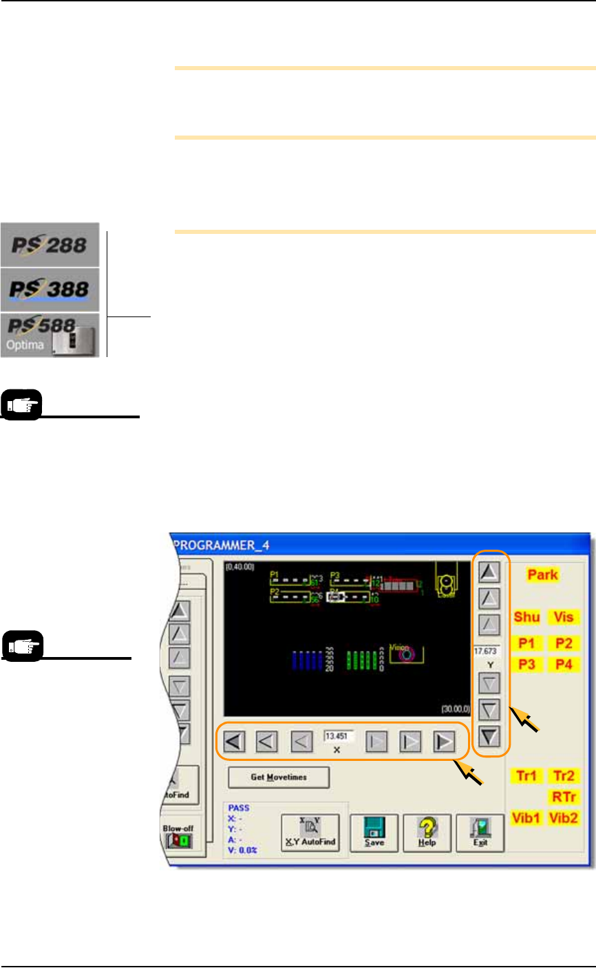
3e. If necessary, adjust the position of the probe so that it is centered
over the device in Pv. Use the X and Y-axis arrows (along the bot-
tom and right side of the black work area) so the probe is cen-
tered over the device.
3f. Save, and click Yes to overwrite the previous values.
Figure 3-27: The Arrow Buttons (circled) on the Gantry Window: From
the center working outboard, the arrow buttons adjust the probe
position ±0.001, 0.010, and 0.100 inches respectively. (PS388 shown.)
A Gantry Window posi-
tion label blinking RED &
YELLOW indicates the
location of the PNP head.
Your model may display
the yellow labels differ-
ently than shown here.