PS288_PS388_PS588_981-0424-002D - 第106页
Operation ■ Administrator Functions 3—36 Data I/O • 981-0424-002 back 4. T each the Z-value (pick height)— 4a. Click Z A utoFind: the probe lowers t o the device (to set the vertical distance) and then click Ye s . 4b. R…
■ Administrator Functions ◘ Teaching the Reference Vision File
PS Series Owner’s Manual 3—35
back
online Help for instructions editing the WinAH400.int file. For an
image of the Setup Window, see Figure 3-20 on page 3–18.
2d. Click System. If asked to enter password, click OK. Open the
Security Dialog and enter your password.
Note: If you don’t have a user profile, either have a supervisor
enter the correct password, or have them create a new User and
Password for you. Use the drop-down arrow, select your new user.
Click System and enter your password. See Creating Security Pro-
files on page 3-31.
2e. Click Gantry.
3. Center the probe over the device: rough-in and then more
accurately—
3a. [PS288, PS388, PS588 Optima] Ensure that the Socket Opener
ribs are adjusted for the current Socket Adapter. For instruc-
tions, see Adjust Socket Opener Ribs on page 3-41.
3b. Click Park (a yellow label).
3c. Manually place a device into socket 1 of the programmer closest
to the Vision camera. (We'll call it Pv, where v is the programmer
number closest to Vision.)
3d. Click label Pv.
3e. If necessary, adjust the position of the probe so that it is centered
over the device in Pv. Use the X and Y-axis arrows (along the bot-
tom and right side of the black work area) so the probe is cen-
tered over the device.
3f. Save, and click Yes to overwrite the previous values.
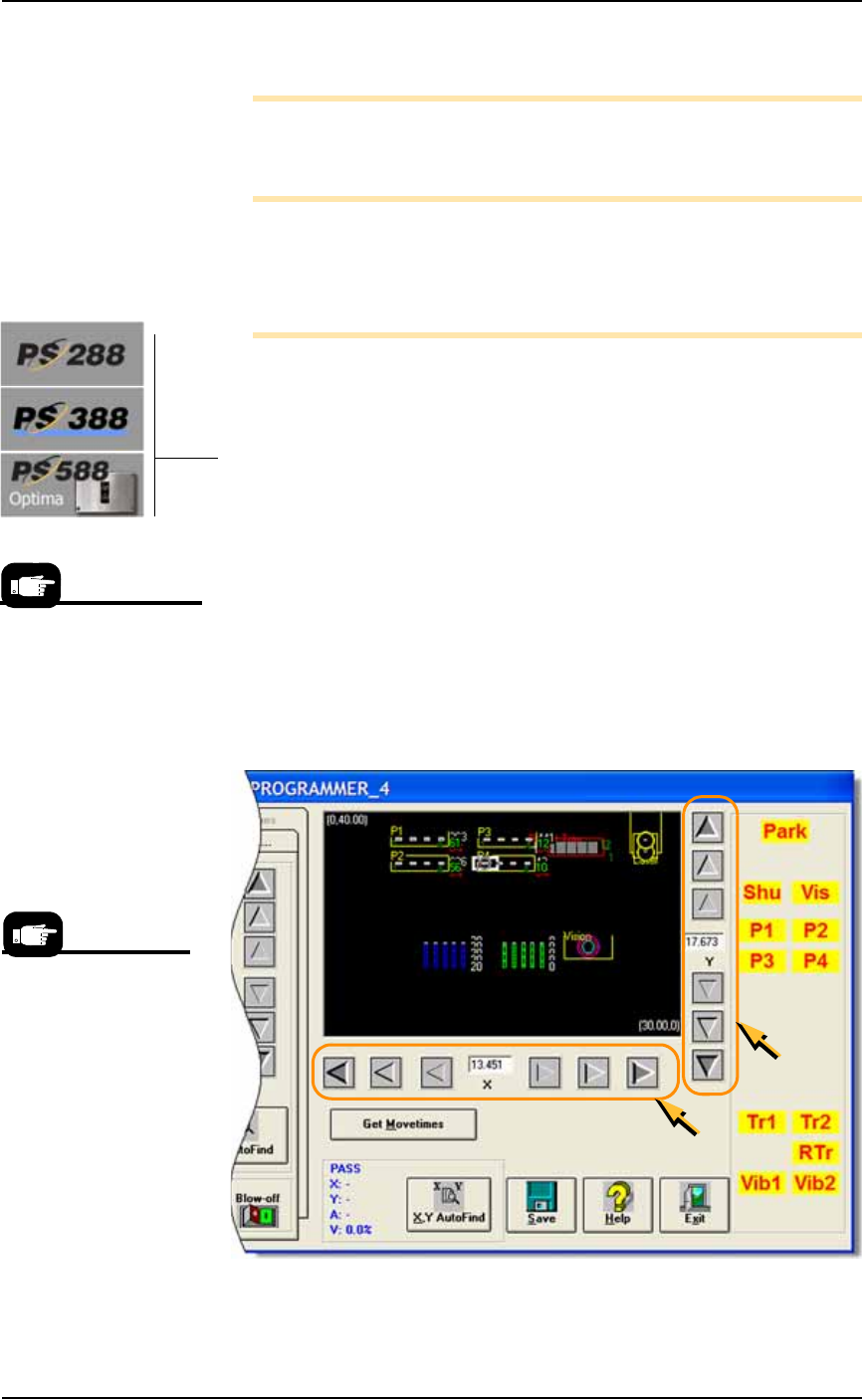
Figure 3-27: The Arrow Buttons (circled) on the Gantry Window: From
the center working outboard, the arrow buttons adjust the probe
position ±0.001, 0.010, and 0.100 inches respectively. (PS388 shown.)
A Gantry Window posi-
tion label blinking RED &
YELLOW indicates the
location of the PNP head.
Your model may display
the yellow labels differ-
ently than shown here.
Operation ■ Administrator Functions
3—36 Data I/O • 981-0424-002
back
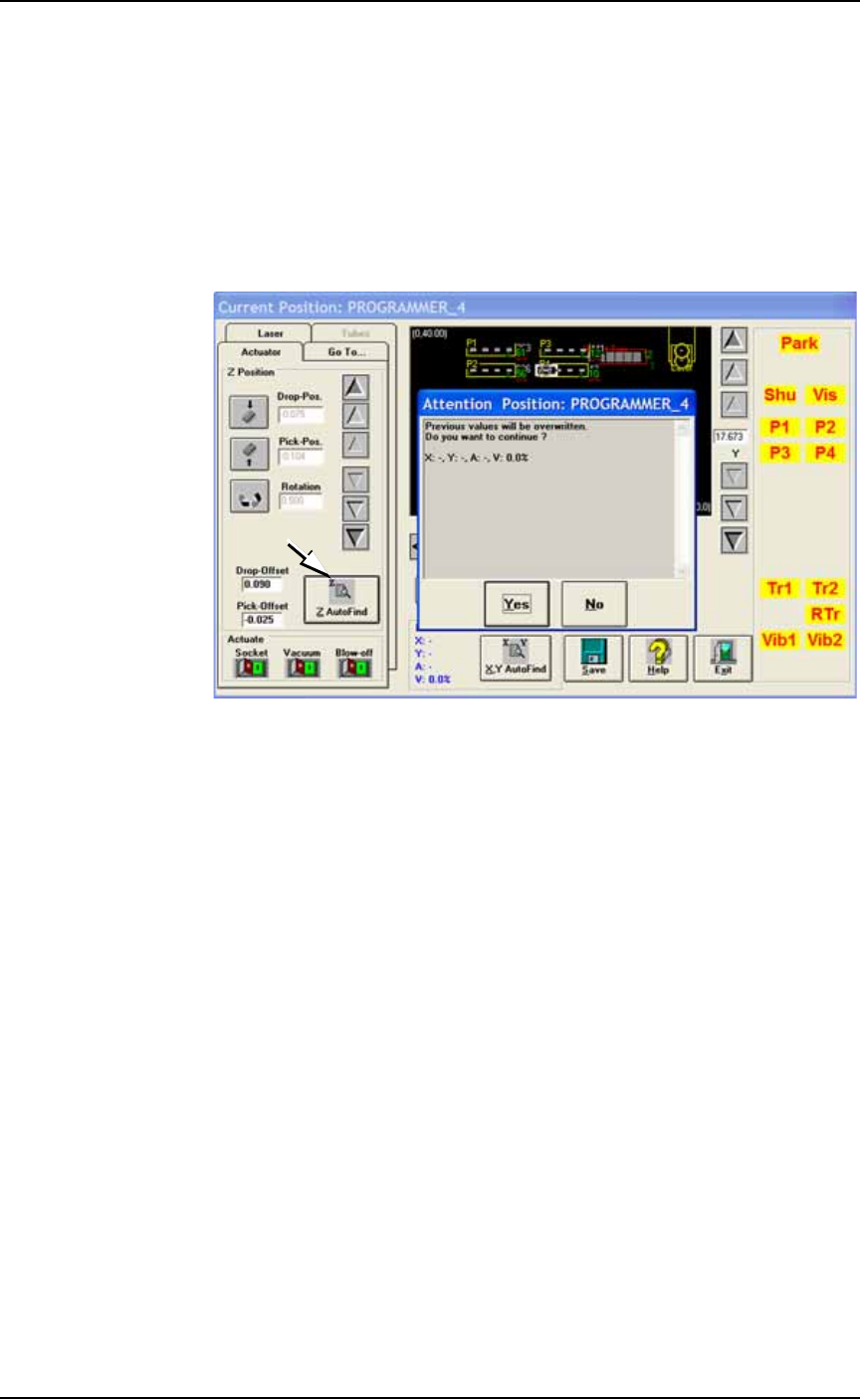
4. Teach the Z-value (pick height)—
4a. Click Z AutoFind: the probe lowers to the device (to set the vertical
distance) and then click Yes.
4b. Right-click on Pv (using the Track Pad buttons) to pick up the
device and visually verify center.
4c. If it is not centered, right-click again to replace the device. Then
repeat the centering process with the X and Y-axis arrows. Click
Save. Pick the device again to recheck center.
If it is centered, right-click again to replace the device.
Figure 3-28: The ZAutoFind button is on the Actuator tab of the Gantry
Window. It uses the probe to determine the Z-value, or height, of a
component. (PS388 shown.)
5. Teach the vision system—
5a. With a device still in socket 1 of the programmer nearest the
vision camera (we’ll call it Pv), right-click label Pv to pick up the
device.
5b. Click the Go To tab.
■ Administrator Functions ◘ Teaching the Reference Vision File
PS Series Owner’s Manual 3—37
back
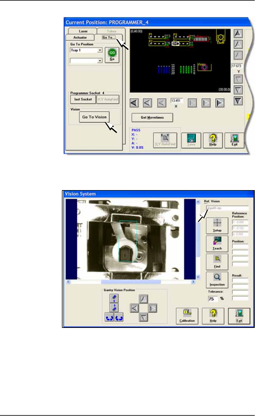
Figure 3-29: The Go To Vision button on the Go To tab.
5c. Click Go To Vision: opens the Vision System dialog. Verify your
new file name in the file name field.
Figure 3-30: The Vision System dialog displays the name of the current
vision file (arrow).
5d. Click Setup.
5e. Click the blue box in the image to select it. Click one of the cor-
ners and drag it to fit around the device.