PS288_PS388_PS588_981-0424-002D - 第108页
Operation ■ Administrator Functions 3—38 Data I/O • 981-0424-002 back Figure 3-31: The Vision Syst em dialog. Resize the blue box b y dragging the handle. 5f. Click Te a c h . Figure 3-32: The Vision System dialog. The T…
■ Administrator Functions ◘ Teaching the Reference Vision File
PS Series Owner’s Manual 3—37
back
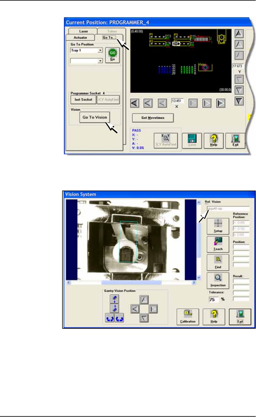
Figure 3-29: The Go To Vision button on the Go To tab.
5c. Click Go To Vision: opens the Vision System dialog. Verify your
new file name in the file name field.
Figure 3-30: The Vision System dialog displays the name of the current
vision file (arrow).
5d. Click Setup.
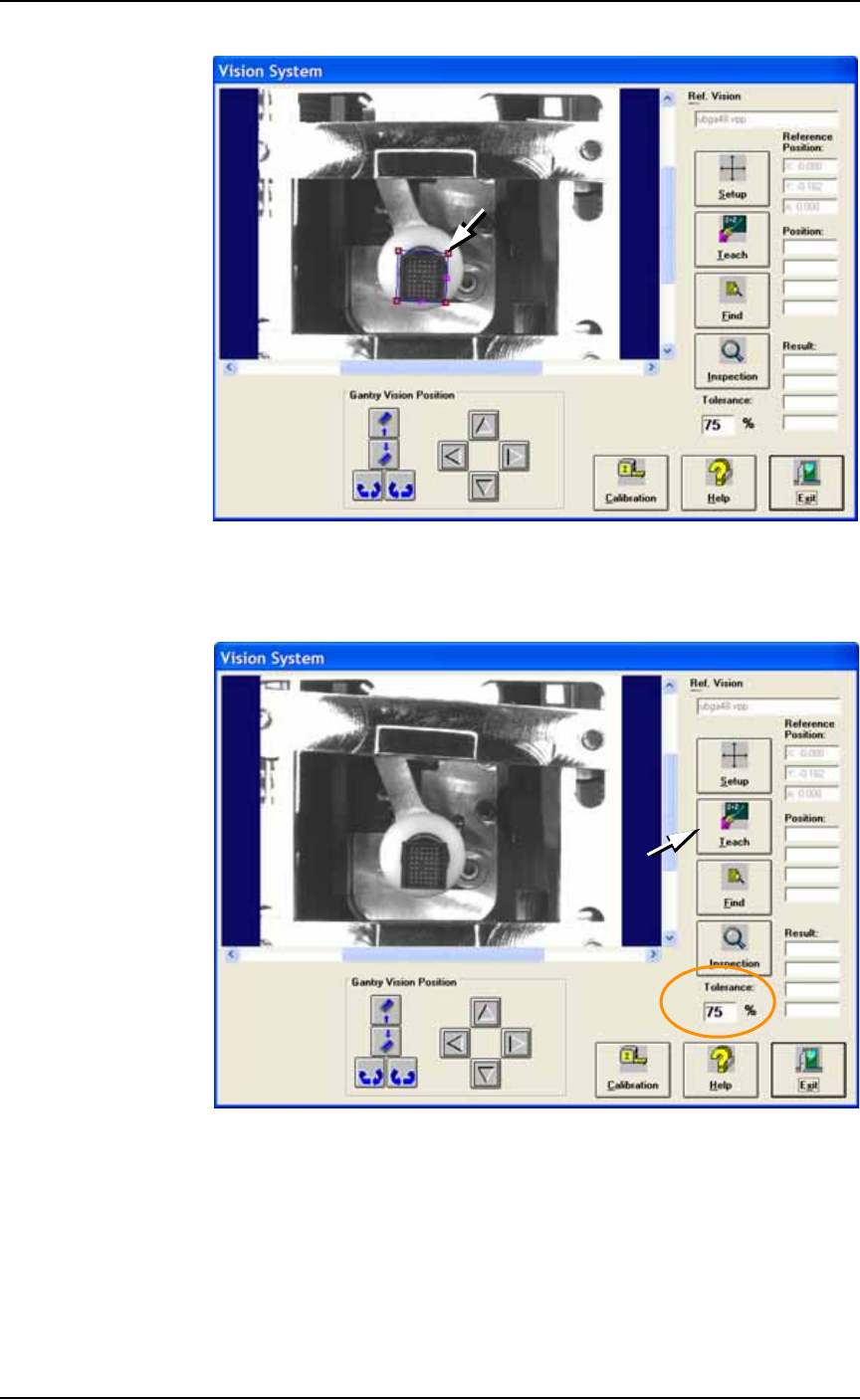
5e. Click the blue box in the image to select it. Click one of the cor-
ners and drag it to fit around the device.
Operation ■ Administrator Functions
3—38 Data I/O • 981-0424-002
back
Figure 3-31: The Vision System dialog. Resize the blue box by dragging
the handle.
5f. Click Teach.
Figure 3-32: The Vision System dialog. The Tolerance is set to 75%
(circled). Click Teach.
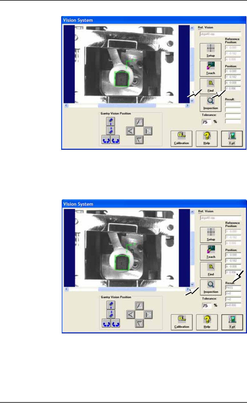
5g. Click Find.
5h. Verify that the device is within the green box and that the ‘V’
value is greater than the tolerance percentage. The V value
should be between 0.900–1.000. For QFPs or very small devices,
the V value may deviate from this range.
■ Administrator Functions ◘ Teaching the Reference Vision File
PS Series Owner’s Manual 3—39
back
Figure 3-33: The Vision System dialog. Verifying the Position V value
after having clicked Find. In this sample, the V value is 99.6%.
5i. Click Inspection.
5j. In the Results field, verify that it reads PASS, and that X, Y and A
are all 0 (zero).
Figure 3-34: The Vision System dialog. Click Inspection and check
Results
5k. Click Exit.
5l. Click Park and remove the device from the programmer.