PS288_PS388_PS588_981-0424-002D - 第112页
Operation ■ Administrator Functions 3—42 Data I/O • 981-0424-002 back 3. Set V ision Rotation to Zero 3a. Click the Vis label. 3b. Click the Actu ator tab and then t he Rotation button. 3c. Enter 0.0, press Enter on the …
■ Administrator Functions ◘ Teaching the Package File
PS Series Owner’s Manual 3—41
back
Adjust Socket Opener Ribs
Note: Adjust the Socket Opener only if the socket fails to open or
if devices are dropped. It is necessary to adjust the Socket Opener
only once while teaching a package file.
Adjust the Socket Opener Ribs as described at Adjust Socket Opener
Ribs on page 3-14.
WARNING: Possible collision hazard. Stay clear of the operating
envelope while teaching PNP head locations except as directed.
The PNP head can move without notice.
Setting Programmer Rotation
1. Setting Programmer Rotation to Zero
1a. At the Gantry Window click Park.
CAUTION: Pinch Hazard. Sockets can actuate even with an
Access Door open. Push the E-Stop prior to working near the
actuators.
1b. Manually insert a device into the first and last sockets of all pro-
grammers intended for use with this job.
To open the sockets on PS588 FlashCORE programmers:
1) Click the label for the programmer, 2) Click the Actuate Socket
toggle to ON (on the Actuate tab), 3) Click the next programmer
label, and repeat.
1c. Click P1.
1d. Click the Rotation button, enter 0.0, press Enter on the keyboard.
1e. Click Save and Yes.
1f. Click Z-AutoFind, then Yes.
1g. Click P1 and then click X,Y AutoFind.
If the resultant values are less than the absolute value of 5, then
click NO. Otherwise click Yes and repeat from Step 1d.
1h. Click the Go To tab.
1i. Click [Go] Last Socket, then the X,Y AutoFind button next to it.
If the resultant values are less than the absolute value of 5 click
NO. Otherwise Yes and repeat.
1j. Repeat step 1a–1i for all programmers.
If an error button appears
on the Gantry window
while teaching the pack-
age file, see Errors on
page 3-50

Operation ■ Administrator Functions
3—42 Data I/O • 981-0424-002
back
3. Set Vision Rotation to Zero
3a. Click the Vis label.
3b. Click the Actuator tab and then the Rotation button.
3c. Enter 0.0, press Enter on the keyboard.
3d. Click Save and Yes.
2. (Optional) recommended check—
2a. Right-click the yellow label for label P1 again.
2b. Press X,Y AutoFind.
2c. When the results appear, note the new values for X and Y. Click
No (to keep the previous values).
2d. Repeat Step 2b two more times and watch the results. Click No
each time to keep the previous values. If the resulting values
gradually increase to more than ±5, the camera may need cali-
bration. See Calibrating The Vision System on page 4-50.
■ Administrator Functions ◘ Teaching the Package File
PS Series Owner’s Manual 3—43
back
Setting Input Media Rotation
When a device is inserted into a socket, pin 1 must match pin 1 loca-
tion of the socket.
CAUTION: Possible socket and device damage. Devices and sock-
ets can be damaged if the devices in the input media are not
delivered to the sockets with the correct pin-1-orientation defined
in the job (via the Package file). Visually ascertain that rotation
information in the Package file is accurate. If it is not, do not start
the job until you either modify the Vision file or re-orient the
devices in the input media. See the steps for setting input media
rotation in the Package File below.
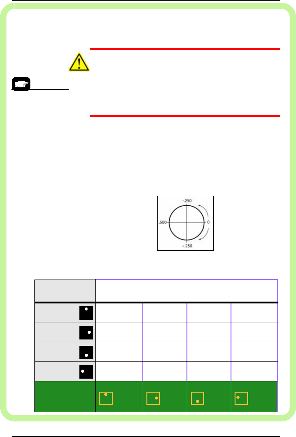
Rotation Values
When teaching the Package File, you are asked to enter the R-axis
rotation value for input media (such as devices in a tray) so that
pin 1 on the device will match pin 1 on the socket; use the fol-
lowing chart.
For example, if a device must be rotated a quarter turn in the clock-
wise direction as it goes from the input media to the socket, set the
R-axis at the socket to -0.250.
Figure 3-35: R-axis values for amount of rotation (not position) from
input media only. Output media is usually the same as the input media.
Pin 1 on most Data I/O
Socket Adapters is
away from the operator
(toward the back of the
machine.)
Pin 1 at my input
media is
Set rotation at input media to . . .
(Set rotation at output media the same as input media.)
Far side
.000 .250 .500 –.250
Right side
–.250 .000 .250 .500
Near side
.500 –.250 .000 .250
Left side
.250 .500 –.250 .000
Pin 1 on my
programmer
sockets is
Far side Right side Near side Left side