PS288_PS388_PS588_981-0424-002D - 第115页
■ Administrator Functions ◘ Teaching the Package File PS Series Owner’s Manual 3—45 back Figure 3-3 7 : After clicking X,Y AutoFind, a confirmation dialog displa ys the results. (PS588 shown.) 2. Set location for the opp…
Operation ■ Administrator Functions
3—44 Data I/O • 981-0424-002
back
Setting Values for Trays
The PS System can have static tray or Automatic Tray Feeder (TF20)
input and output modules. Teaching tray locations is the same for
both.
Note: If the Automatic Tray Feeder option is installed, trays dis-
played in the Gantry Window are oriented as shown in Figure 3-36.
Figure 3-36: Gantry Window shown with an automatic tray feeder
installed. (PS588 shown.)
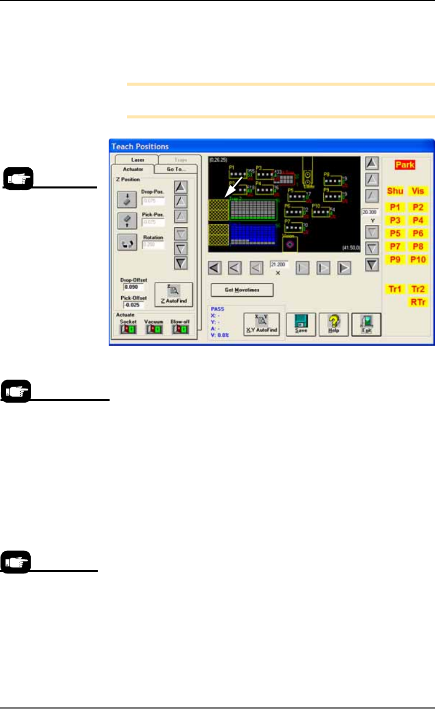
1. Setting X, Y, Z & R values for Trays—
1a. Click Park. Then manually place a device in each corner pocket
of the trays. (Devices in other pockets are okay.)
1b. Click Tr1: sends the probe to the left corner device in Tray 1.
1c. If necessary, center the probe over the device. Use the X and
Y-axis arrows (along the bottom and right side of the black work
area) so the probe is centered over the device.
1d. Click Save, and Yes.
1e. Click Z AutoFind (to set the vertical distance to the device) and
then Yes to save the value.
1f. Click Rotate icon.
1g. Type the desired rotation into the rotate field and press Enter on
the keyboard. See Rotation Values on page 3-43 for more informa-
tion.
1h. Save and click Yes.
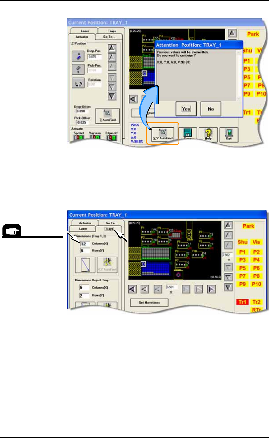
1i. Press X,Y AutoFind. When the results appear, verify that the new
values for X and Y are less than ±5. If so, click No (to keep the
previous values).
If new values are greater than ±5, click Yes to use these new val-
ues. Then recheck (by clicking X, Y AutoFind again).
On-screen Label
abbreviations:
Tr1- Tray 1,
RTr- Reject Tray
Vib1- Vibrator 1
Vis- Vision Camera
If you are using one tray for
both input and output for
this job, then only that one
tray needs to be taught.
X,Y AutoFind sends the
probe to the vision cam-
era and compares the
device image with the
reference vision file.
■ Administrator Functions ◘ Teaching the Package File
PS Series Owner’s Manual 3—45
back
Figure 3-37: After clicking X,Y AutoFind, a confirmation dialog displays
the results. (PS588 shown.)
2. Set location for the opposite corner of tray 1—
2a. Click the Trays tab.
2b. Enter the number of columns and rows for this tray. See Figure
3-38.
Figure 3-38: Enter tray rows and columns on the Trays tab of the
Gantry Window. (PS588 shown.)
2c. Click the opposite corner button (the diagonal arrow): The probe
moves to the opposite corner of the tray.
2d. If necessary, adjust the position of the probe so that it is centered
over the device. Use the X and Y-axis arrows (along the bottom
and right side of the black work area) so the probe is centered
over the device.
2e. Click X,Y AutoFind. When the results appear, verify that the new
values for X and Y are less than ±5. If so, click No (to keep the
previous values).
Which are Rows and
which are Columns?
As tray orientation may
be different, always enter
the lines in the X-axis
direction into the first
field labeled COL-
UMNS(X).
Operation ■ Administrator Functions
3—46 Data I/O • 981-0424-002
back
If new values are greater than ±5, click Yes to use these new val-
ues. Then repeat the comparison (by clicking X, Y AutoFind
again).
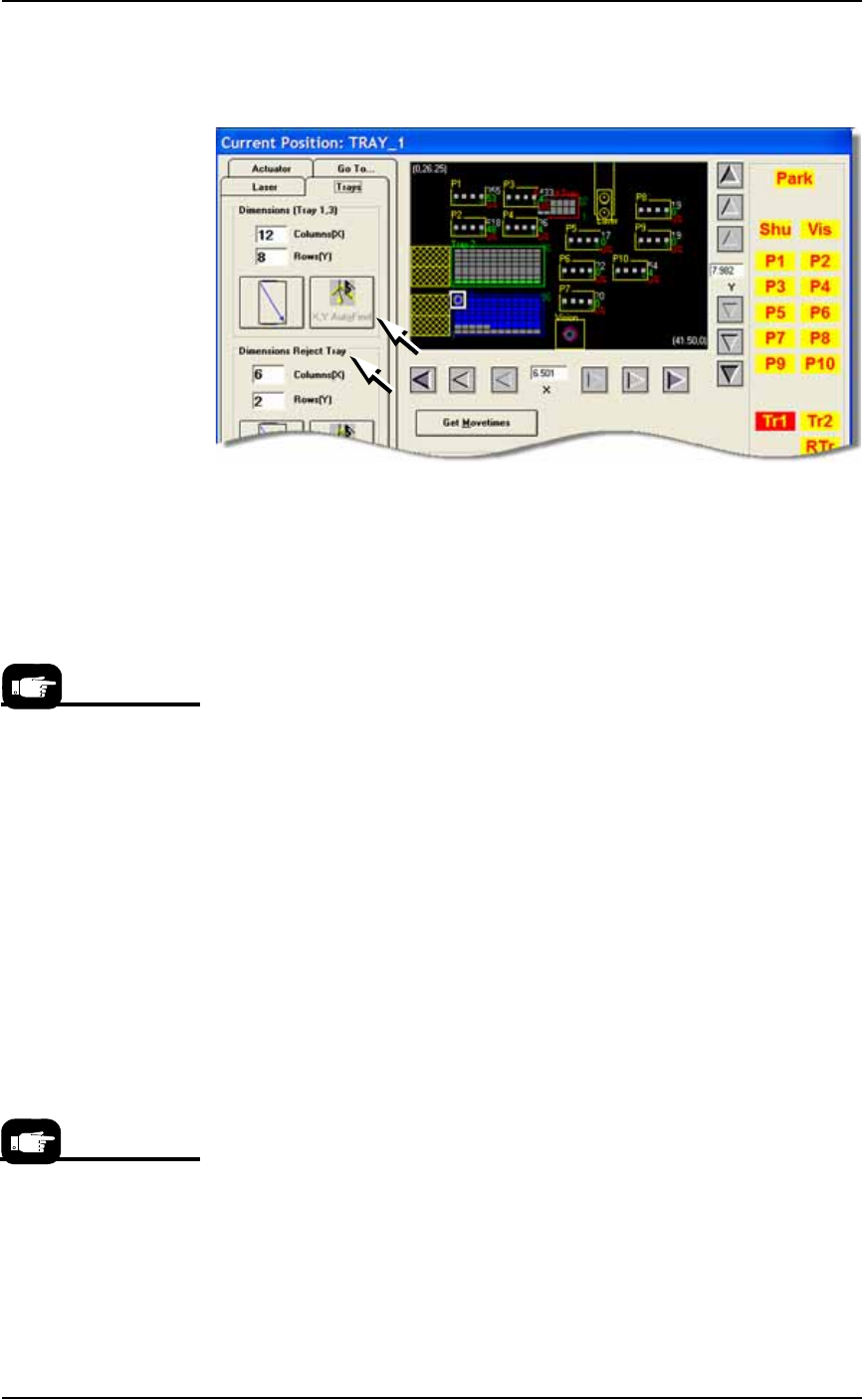
Figure 3-39: The X,Y AutoFind button for trays is on the Trays tab, as
well as Reject (Bin) Tray information. (PS588 shown.)
3. Repeat Step 1 and Step 2 above for Tray 2 if using Tray 2.
Set R-value the same as Tray 1.
Setting Values for the Reject Tray
Teach Reject Tray location—
1. Click RTr. If necessary, adjust the probe location using the X and
Y-axis arrows (along the bottom and right side of the black work
area, respectively) to align the probe with the far left corner of
the Reject Tray.
2. Click Save and Yes.
3. Click the Trays tab.
4. In the Dimensions Reject Tray fields, enter a value for
Columns (X) and Rows (Y) for the Reject Tray. These values set
the maximum number of devices that can be sent to the Reject
Tray before the displaying the message Reject is Full. In Figure
3-39, the message will display after 12 (6 x 2) devices are placed
in the Reject Tray.
5. Click the diagonal arrow. The PNP head moves to the nearest
right corner of the Reject Tray. If necessary, adjust the probe loca-
tion using the X and Y-axis arrows (along the bottom and right
side of the black work area, respectively) to align the probe with
the nearest right corner of the Reject Tray.
6. Click X-Y AutoFind (in the Dimension Reject Tray field) and then
Yes to overwrite values if within ±5.
Setting Values for Tubes
1. Center the probe at Vib1 and set Z—
1a. At the Gantry window, click Vib1.
From the inside working
outward, the axis arrow
buttons adjust the probe
position ±0.001, 0.010,
and 0.100 inches respec-
tively.
For information on select-
ing Vibrator Tube media
in the Setup Window, see
Set Media and
Options—the Setup Win-
dow on page 3-16.