PS288_PS388_PS588_981-0424-002D - 第118页
Operation ■ Administrator Functions 3—48 Data I/O • 981-0424-002 back 3g. If the new values for X and Y are greater than ±5, press Ye s and repeat Step 3e to Step 3f. If the new v alues for X and Y are less than ±5, pres…
■ Administrator Functions ◘ Teaching the Package File
PS Series Owner’s Manual 3—47
back
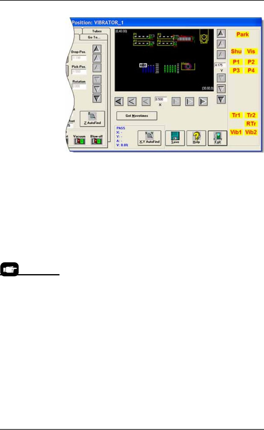
Figure 3-40: The white rectangle (representing the PNP head) is at
Vib1 location. (PS388 shown.)
1b. If necessary, adjust the position of the probe so that it is centered
over the device in the staging area of the left-most tube of Vibra-
tor 1. Use the X and Y-axis arrows (along the bottom and right
side of the black work area) to center the probe over the device.
1c. Click Save and Yes.
1d. Click Z AutoFind (to set the vertical distance to the device) and
then Yes to save the value.
2. Set Rotation at Vibrator (Tubes)—
2a. Click Rotate button.
2b. Type the desired rotation into the rotate field and press Enter on
the keyboard. See Rotation Values on page 3-43 for more informa-
tion.
2c. Save and click Yes.
2d. Click X,Y AutoFind. When the results appear, verify that the new
values for X and Y are less than ±5. If so, click No (to keep the
previous values).
If new values are greater than ±5, click Yes to use these new val-
ues. Then recheck (by clicking X, Y AutoFind again).
3. Identify and center probe over the right-most tube—
3a. Click the Tubes tab.
3b. In the Columns (X) field, enter the number of tubes in Vibrator 1.
3c. In the Chips/Tube field, enter the number of devices per tube.
3d. Click the Diagonal Corner button to move the probe to the
right-most tube in Vibrator 1.
3e. If necessary, adjust the location of the probe so that it is centered
over the device in the staging area of the right-most tube. Use
the X and Y-axis arrows (along the bottom and right side of the
black work area) to center the probe over the device.
3f. Click X,Y AutoFind (adjacent to the Diagonal Corner button).
X,Y AutoFind sends the
probe to the vision cam-
era and compares the
device image with the
reference vision file.

Operation ■ Administrator Functions
3—48 Data I/O • 981-0424-002
back
3g. If the new values for X and Y are greater than ±5, press Yes and
repeat Step 3e to Step 3f.
If the new values for X and Y are less than ±5, press No.
4. Teach Vibrator 2 locations—
4a. At the Gantry window, click Vib2.
4b. Repeat these steps (1b–3g) for Vibrator 2.
Set R-value the same as Vibrator 1.
Setting Values for the Shuttle
1. Positioning the Shuttle—
1a. Exit the Gantry Window.
1b. At the System Window click Shuttle/Options.
1c. Click Home.
1d. After the head stops moving, click the first Go button (adjacent
to the Ped 2 Load Pos).
1e. Click Exit. Then at the System Window, click Gantry.
2. Teach locations—
2a. At the Gantry Window, click Shu to move the PNP head to the
marking shuttle.
2b. If necessary, adjust the location so the probe is centered on Ped-
estal 2. Use the X and Y-axis arrows (along the bottom and right
side of the black work area) to center the probe on the pedestal.
2c. Click Save and Yes.
3. Placing a device on Shuttle 2—
3a. Click Park to move the PNP head to the Park location.
3b. Click the Shuttle/Options tab. (In some machines/configurations,
this tab may say Laser.)
3c. Turn the Vacuum button to ON if it is not already.
3d. Manually place a device on shuttle Pedestal 2.
3e. Click the Actuator tab.
4. Set Z & R values—
4a. Click Shu.
4b. Click ZAutoFind and Yes.
4c. Click Rotate button.
4d. Type the desired rotation into the rotate field and press Enter on
the keyboard. See Rotation Values on page 3-43 for more informa-
tion.
4e. Save and click Yes.
5. Remove the device from Shuttle 2—
5a. Click Park.
5b. Click the Shuttle/Options tab.
5c. Turn the Vacuum button to OFF.
5d. Manually remove the device from shuttle Pedestal 2.
5e. Click the Actuator tab.
6. Accurately centering the probe —
6a. Click label Shu to move the probe to the marking shuttle.
■ Administrator Functions ◘ Teaching the Package File
PS Series Owner’s Manual 3—49
back
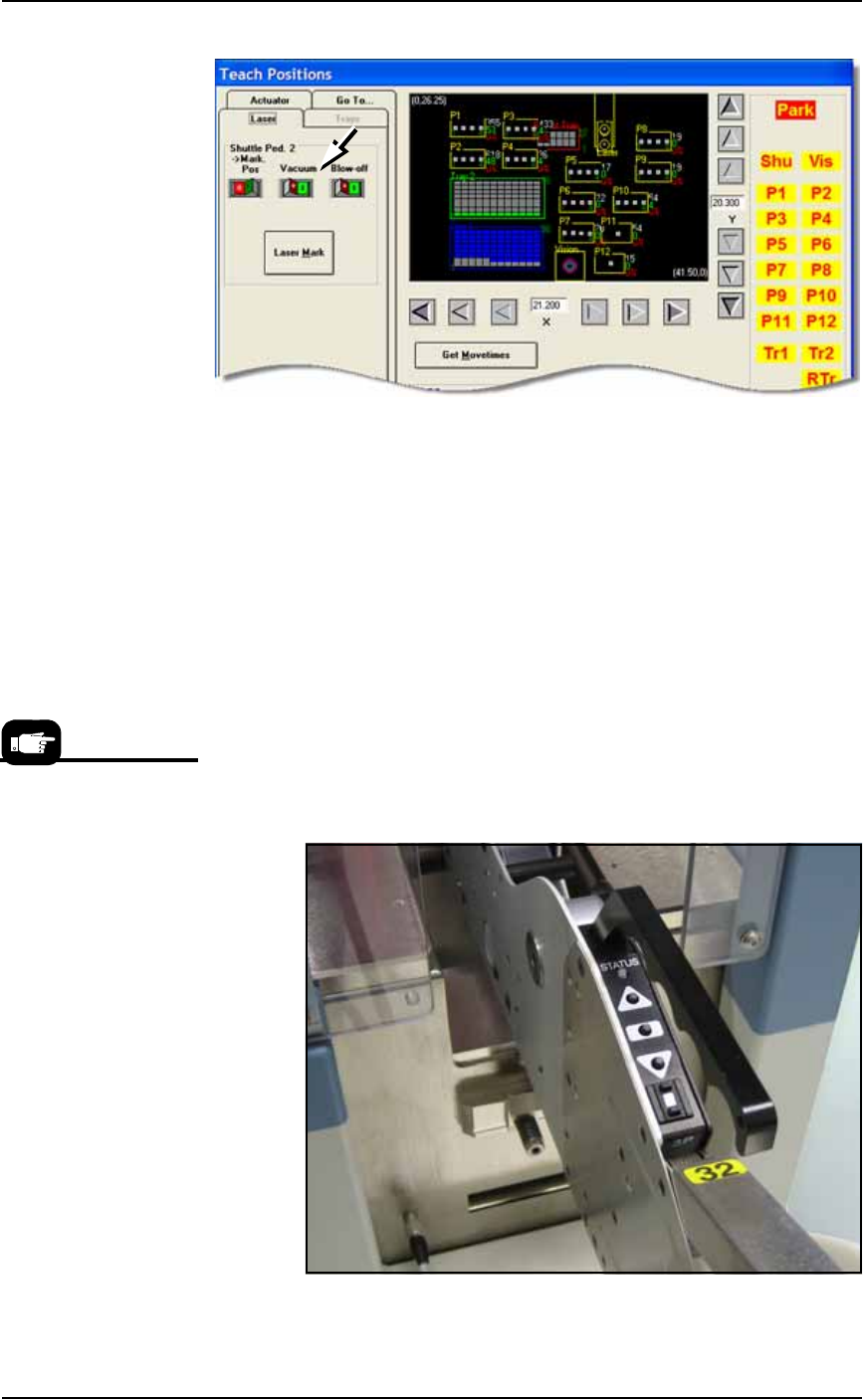
Figure 3-41: Vacuum switch on the Laser tab (or Shuttle/Options tab).
(PS588 Gantry Window shown.)
6b. Click the Pick Pos button to lower the probe.
6c. If necessary, adjust the location so the probe is centered on Ped-
estal 2. Use the X and Y-axis arrows (along the bottom and right
side of the black work area) to center the probe on the pedestal.
6d. Click Save and Yes.
6e. Click the Pick Pos button again to raise the probe.
Setting Values for Tape-Input
With the chip feeder installed and the pocket pitch set correctly:
1. Advance the chip feeder—
1a. On the chip feeder control panel, while pressing and holding the
center button, press the forward button. The carrier tape
advances one guide hole. Advance the carrier tape until the cen-
ter of the device aligns with the pick point mark.
Figure 3-42: A chip feeder mounted on a PS388.
For more information, the
Operator Guide that
came with your Chip
Feeder.