PS288_PS388_PS588_981-0424-002D - 第120页
Operation ■ Administrator Functions 3—50 Data I/O • 981-0424-002 back 2. T each locations— 2a. At the Gantry window , click Ta p e to move the probe to the tape input pick position. 2b. If necessary , adjust the location…
■ Administrator Functions ◘ Teaching the Package File
PS Series Owner’s Manual 3—49
back
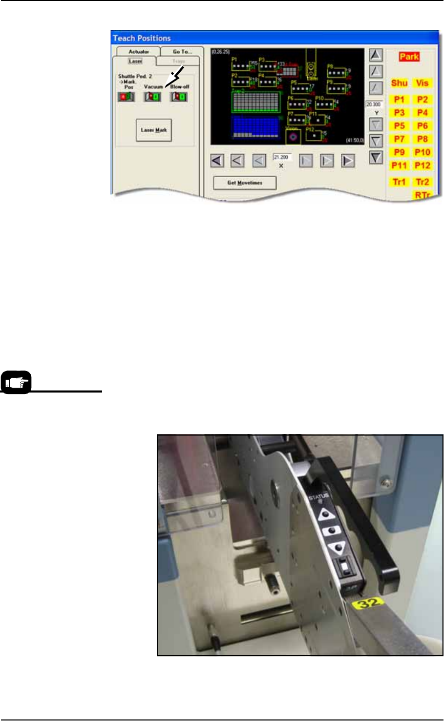
Figure 3-41: Vacuum switch on the Laser tab (or Shuttle/Options tab).
(PS588 Gantry Window shown.)
6b. Click the Pick Pos button to lower the probe.
6c. If necessary, adjust the location so the probe is centered on Ped-
estal 2. Use the X and Y-axis arrows (along the bottom and right
side of the black work area) to center the probe on the pedestal.
6d. Click Save and Yes.
6e. Click the Pick Pos button again to raise the probe.
Setting Values for Tape-Input
With the chip feeder installed and the pocket pitch set correctly:
1. Advance the chip feeder—
1a. On the chip feeder control panel, while pressing and holding the
center button, press the forward button. The carrier tape
advances one guide hole. Advance the carrier tape until the cen-
ter of the device aligns with the pick point mark.
Figure 3-42: A chip feeder mounted on a PS388.
For more information, the
Operator Guide that
came with your Chip
Feeder.

Operation ■ Administrator Functions
3—50 Data I/O • 981-0424-002
back
2. Teach locations—
2a. At the Gantry window, click Tape to move the probe to the tape
input pick position.
2b. If necessary, adjust the location so the probe is centered on pick
point. Use the X and Y-axis arrows (along the bottom and right
side of the black work area) to center the probe on the pick
point.
2c. Click Save and Yes.
2d. Click Z AutoFind (to set the vertical distance to the device) and
then Yes to save the value.
3. Set Rotation at Tape Input—
3a. Click Rotate button.
3b. Type the desired rotation into the rotate field and press Enter on
the keyboard. See Rotation Values on page 3-43 for more informa-
tion.
3c. Save and click Yes.
3d. Click X,Y AutoFind. When the results appear, verify that the new
values for X and Y are less than ±5. If so, click No (to keep the
previous values).
If new values are greater than ±5, click Yes to use these new val-
ues. Then recheck (by clicking X, Y AutoFind again).
This completes the process of teaching the Package File.
Errors
Axis Limit Error
During the process of teaching the Package File, you will be directing
the PNP head to move to various locations inside the work envelope.
If the PNP head is directed to move beyond its X-axis or Y-axis limits,
you will see a red error button.
To resolve axis limit errors:
1. Record error message—
1a. Note what item was being taught when the error appeared, such
as Programmer 5 or Tray 1 or Tube 2.
1b. Click the Error button to display the error message.
X,Y AutoFind sends the
probe to the vision cam-
era and compares the
device image with the
reference vision file.
■ Administrator Functions ◘ Get Movetimes/Optimize Movetimes
PS Series Owner’s Manual 3—51
back
.
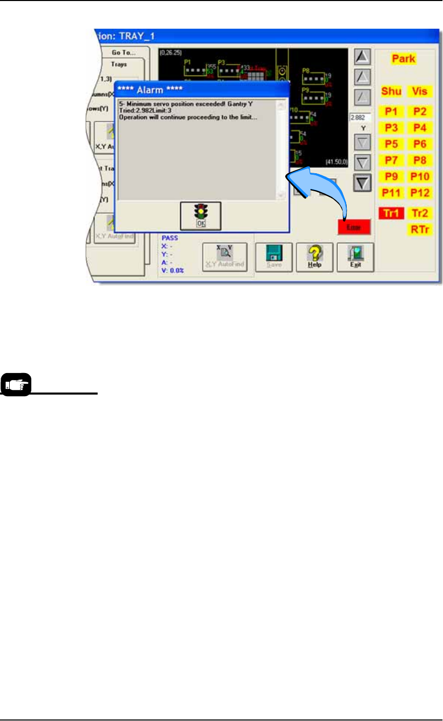
Figure 3-43: Error messages don’t display unless you click the red Error
button to open the Alarm dialog. (PS588 Gantry Window shown.)
1c.
Write down the axis (in this case, Y-axis), whether the min-
imum or maximum position has been exceeded (in this
case, the minimum position), and the “Tried” and “Limit”
values (in this case, Tried = 2.982 and Limit = 3).
1d. Click OK.
2. Contact Data I/O Service or your nearest authorized represen-
tative—
3. The item that was being taught when the error occurred (tray,
programmer, reject bin, etc.) needs to be re-taught. See Teach-
ing the Package File starting on page 3-40.
Get Movetimes/Optimize Movetimes
When the Package File and Reference Vision File are taught, you can
optimize the movement of the PNP head in the work envelope by get-
ting movetimes. This command calculates the best PNP path, espe-
cially when some programmers are not used, and considers
programming times versus head travel time.
To get movetimes:
1. Gantry—
1a. On the Gantry Window, click Optimize Movetimes (older versions
read Get Movetimes.
For contact
information see
Contacting Data I/O
on page ix.