PS288_PS388_PS588_981-0424-002D - 第126页
Operation ■ Administrator Functions 3—56 Data I/O • 981-0424-002 back Note: In the above example the SPC logging file is saved to C:\ directory . It can, however , be saved anywhere on the Handler Com- puter hard drive, …
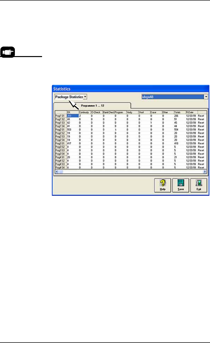
■ Administrator Functions ◘ Monitoring Statistics
PS Series Owner’s Manual 3—55
back
1. Select Package Statistics in drop-down field in the upper left
corner.
2. Click Reset in the right-most column corresponding to the
FlashCORE programmer on which the Socket Adapter was
replaced.
• If a Socket Adapter was replaced, reset all rows for that pro-
grammer.
• If an individual socket was replaced*, reset only the row corre-
sponding to the replaced socket.
The R-date (reset date) is set to the current date and statistics are
reset to all zeroes.
Figure 3-48: Resetting Package statistics.
Statistical Process Control Software
Most SPC (Statistical Process Control) Software (customer-supplied)
can import a comma-delimited file. AH500 can be set to generate a
comma-delimited file whose fields are described on the next page.
To generate a comma-delimited output file:
1. Enable file generation for SPC software—
1a. On the Handler Computer, navigate to C:\AH500 and open
winAH400.ini with Microsoft Notepad (or IDM Computer Solu-
tions’s UltraEdit).
1b. Locate the section for SPC Logging. It will look like this:
[SPC Logging]
LoggingEnabled=FALSE
MaxFileSize=10485760
TempLogFile=C:\spcout.txt
1c. Set the second line (LoggingEnabled) to TRUE.
1d. Save and close winAH400.ini.
*Only HIC Socket
Adapters and HPS
Socket Adapters are
designed to accommo-
date replacement of
individual sockets on
the adapter board.

Operation ■ Administrator Functions
3—56 Data I/O • 981-0424-002
back
Note: In the above example the SPC logging file is saved to
C:\
directory. It can, however, be saved anywhere on the Handler Com-
puter hard drive, or on a networked drive if the PS System is con-
nected to a network.
The SPCOut.txt file contains 19 semicolon-delimited fields, as fol-
lows:
The SPCOut.txt Field Descriptions
01 DevicesInputsystem - number of devices picked from Input
media
02 DevicesInspected - number of devices inspected by Vision system
03 InspectionQuality - as percentage, compared with reference
vision
04 InspectionYield
05 DevicesInsertedSocket - number of devices inserted into socket
06 SocketYield
07 ProgrammerYield
08 ProgSysYield - Yield of all programmers together
09 DevicesProcessedMarker
10 MarkingYield
11 SystemThroughputExcWait - starts with first device placed,
excludes wait times.
12 SystemTotalThroughputIncWait - starts when Run starts,
includes wait times
13 SystemYield
14 AreaID - Programmer #1 = “17”, Programmer #2 = “18”, …, Pro-
grammer #24 = “40”)
15 PosID - that is Socket #
16 TimeStamp - Date/Time of SPC log entry
17 OrderNumber - Job Name and or number
18 Package - Package File used for the job
19 VisionVPP - Reference Vision File used for the job

■ Administrator Functions ◘ Maximizing Programming Yields
PS Series Owner’s Manual 3—57
back
Maximizing Programming Yields
Occasional declines in system yields may occur during day to day
operation of the PS System. While overall yield levels can vary
depending on device manufacture, any steep change in yields is suffi-
cient reason for investigation of an immediate cause of variation.
These changes in yield can be attributed to a number of causes,
including device quality control, socket issues, system maintenance,
and process errors.
Quality Control of Devices
Variations in the manufacture of devices may affect yields in an auto-
mated system, such as:
Variation in dimensions from different manufacturing lots or
facilities can cause devices to fit improperly in the sockets or
require reteaching the Package File to be placed successfully.
Presence of residual plastic on the edges of the devices (flashing)
can cause devices to rest improperly in the sockets.
Die changes (shrinks, process improvement for improved wafer
yield, etc.) require new algorithms. Data I/O tracks these
changes with vendors and recommends all customers subscribe
to the algorithm update program.
Die processes contain variability. Programming yields can some-
times vary on a normal die. Device families recently introduced
to the market tend to have more fluctuations in yields as the
semi-vendor's manufacturing process stabilizes.
Multiple fabrication sites often produce the same devices. Per-
formance characteristics, including programming yield, can
vary from location to location.
Lead oxide accumulating on device leads is an issue for some
devices. This can vary with age and the conditions with which
the devices are stored.
Programming yields decrease with the number of programming
cycles. Devices that are processed more than once are more
likely to experience problems.
Socket Issues
The programming sockets are perhaps the most important and vul-
nerable element of the PS System. They are subject to residue
buildup, damage from mis-inserted devices (perhaps due to poor cal-
ibration of the placement system), and general wear and tear.
Socket conditions that cause varying yields include the following:
Debris of any type can prevent sockets from closing completely.
Sometimes the debris may not be visible. Simple actuation may
clear debris, or it may be necessary to clean sockets with low
pressure air.
Blow out sockets every day with clean and dry air at 6.2 Bars (90
PSI) or less. Press down on the opener to blow out debris from
beneath the contacts. More frequent cleaning is recommended in
a dirty environment.
Bent or distorted contact pins can cause intermittent socket fail-
ures.
Socket life is generally
rated by the manufacturer
as the number of inser-
tions per socket after
which yields may drop
significantly.