PS288_PS388_PS588_981-0424-002D - 第137页
■ Printer Options ◘ (Optional) Creating a Laser Marking File PS Series Owner’s Manual 3—67 back V erifying Proper Laser Operation WARNING: Toxic fum e hazard! Laser marking generates vapors, fumes, and particles that may…
Operation ■ Printer Options
3—66 Data I/O • 981-0424-002
back
2a. Start WinMark Pro by double-clicking the WinMark icon on the
desktop.
2b. Click File > Load.
2c. Select a laser marking file from the list, or navigate to the folder
and select the file.
2d. Click Open.
3. The Mark icon—
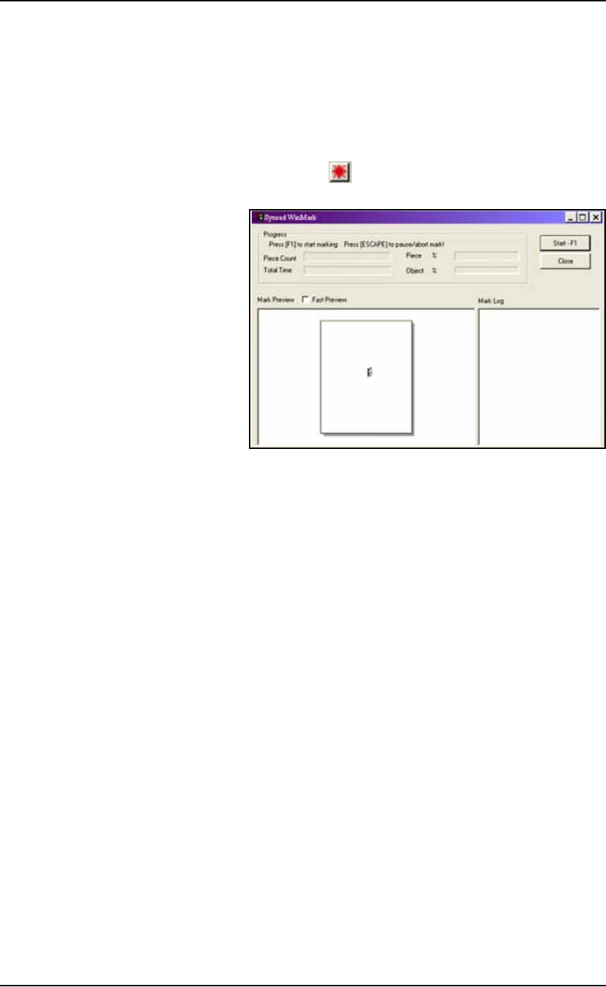
3a. Click the Mark icon in the tool bar at the top of the WinMark
Window: the marking graphic is displayed.
Figure 3-56: The Synrad WinMark Control Window.
3b. Click the Start–F1 button on the screen.
The WinMark software is now ready for commands from the Handler
Computer to begin marking devices.
■ Printer Options ◘ (Optional) Creating a Laser Marking File
PS Series Owner’s Manual 3—67
back
Verifying Proper Laser Operation
WARNING: Toxic fume hazard! Laser marking generates vapors,
fumes, and particles that may be noxious, toxic, or even fatal. Fol-
low maintenance procedures on the fume extractor. Use proper
ventilation.
To verify that the laser is marking as expected:
1. At the Run Window, click RunOne.
Only one device will be processed.
1a. Verify that the marking graphic is centered on the device. If the
graphic is not centered, adjust the laser file. Refer to Figure 3-53
on page 3–63.
WARNING: Blindness hazard! Always wear eye protection when
the laser access doors are open. Direct or diffuse laser radiation
can damage eyes. Goggles must block 10.6
μ
m laser radiation.
Goggles protect against scattered energy but not against direct
viewing of the laser beam or reflections from metallic surfaces.
WARNING: Serious burn hazard! Laser radiation, whether direct
or diffuse, can cause serious burns. Keep hands and other parts of
the body out of the path of the laser beam.
Troubleshooting
If the device is not marked, perform the following USING
EXTREME CAUTION:
1. Remove the access panel on the right end of the Option Bay
when viewing it from the back of the PS System. Use a 1/8 inch
hex key to remove six fasteners.
2. Lay a sheet of white paper in the laser bay over the pedestals.
3. Temporarily disable the panel safety interlock (as with tape).
4. Fire the laser (by clicking Laser Marker on the Shuttle/Options >
Subsystem tab).
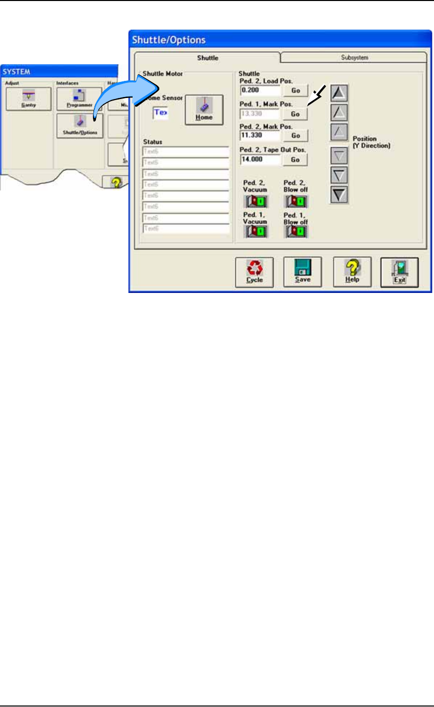
If the mark appears on the paper, make sure the mark is cen-
tered over the shuttle. If the mark placement needs adjustment,
change the Mark Position at the Shuttle/Options > Shuttle tab.
Operation ■ Printer Options
3—68 Data I/O • 981-0424-002
back
Figure 3-57: Adjust the marking position (Mark Pos.) for either
pedestal at the Shuttle/Options Window if necessary.
If no image appears on the paper:
A) Verify power to the laser marking assembly is connected and
turned on.
B) Ensure that the access panel interlock is disabled.
If all appears correct an still no results, contact Data I/O Customer
Support.