PS288_PS388_PS588_981-0424-002D - 第145页
■ Workspace, Head and Gantry ◘ Socket Adapters and Actuation PS Series Owner’s Manual 4—5 back Workspace, Head and Gantry The workspace includes the Sock et Adapters and items on the working surface, but not the Prog ram…
Maintenance ■ Maintenance Schedule
4—4 Data I/O • 981-0424-002
back
Materials Required
To perform preventive maintenance procedures on the PS System,
you need the following materials:
• Lens cleaning paper
• Isopropyl alcohol
• Antistatic cleaner
• Silicone lubrication spray
• Tri-Flow lubricant (Data I/O part number
560-3300-901)
• Dry, compressed air
• Safety goggles
• Disposable protective gloves
•SAE and metric hex socket wrenches and Hex Keys (Allen
wrenches)
• Metric open end wrenches for the probe tips
• Shop vacuum cleaner
• Diagnostic Adapter Board (DAB)
• NSK Grease and Grease Gun MG70
Turning Off the System
When the PS System will not be used for several days, or before per-
forming a service procedure, shut off the system.
1. Complete or exit any job that is running.
2. Remove all devices from the system.
3. [Laser Marker only] Exit the Laser Marker software and shut
off the Laser Computer from the Windows Start menu.
4. Exit AH500 and TaskLink, and shut off the Handler Computer
from the Windows Start menu.
5. WAIT UNTIL WINDOWS COMPLETES SHUTTING DOWN,
then rotate the main power switch (on the back Input Panel)
counterclockwise to the OFF (vertical) position.
6. (Optional) Padlock the main power switch so that it cannot be
turned back on while the lock is in place.
See Chapter 3 for
more information on
exiting a job or shut-
ting off computers.
■ Workspace, Head and Gantry ◘ Socket Adapters and Actuation
PS Series Owner’s Manual 4—5
back
Workspace, Head and Gantry
The workspace includes the Socket Adapters and items on the
working surface, but not the Programmers or Vision System. They
are covered in separate headings.
Socket Adapters and Actuation
Under this heading you will learn about visually inspecting, cleaning
and adjusting sensors and air pressure for the workspace items.
Inspecting the Socket Adapters
The condition of the Socket Adapters has great throughput conse-
quences.
WARNING: Vision hazard. Always use care and wear protective
eye goggles when cleaning with pressurized air. Pressurized air or
debris blown into the eyes or skin could cause bodily damage.
1. Use clean, dry compressed air to remove dirt from the sockets.
2. Check the sockets for wear and replace if necessary.
Note: The socket replacement cycle depends upon the type of socket
used and the socket manufacturer. For life cycle guidelines, refer to
the documentation that came with your sockets.
Adjusting the Socket Actuator Sensors
[PS288, PS388 and Optima Programmers only on PS588] The Socket
Actuator sensor reports the position of the Socket Actuator (up or
down), and therefore controls when a device can be put into a socket.
Note: Sensors are set at the factory. They need adjustment only if
experiencing trouble. One possible indicator of needed adjustment
is an error message such as Socket Opener failed.
A PS588 with Optima Programmer and a Socket Adapter installed
are necessary for this procedure.
PS288 & PS388 require a FlashCORE programmer with a Socket
Adapter installed for this procedure.
To adjust the Socket Actuator sensor:
1. Preparation—
1a. Start the AH500 Application.
Maintenance ■ Workspace, Head and Gantry
4—6 Data I/O • 981-0424-002
back
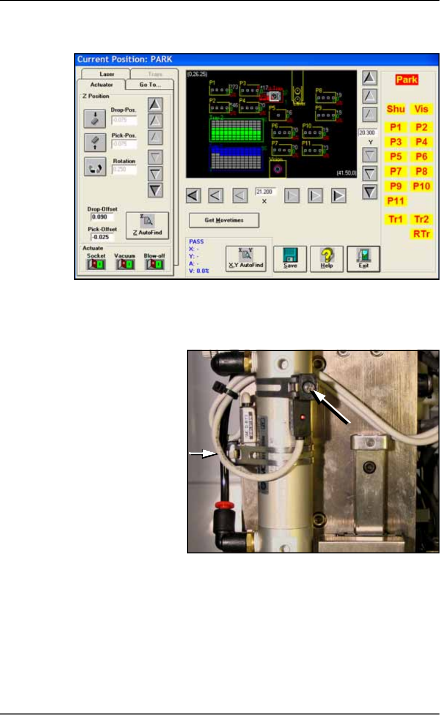
1b. At the Setup window, click System > Gantry. You may need to
enter a password.
Figure 4-1: The Gantry window (PS588 shown).
1c. Click on any programmer label (P1 through P12) that has an
Optima (Universal) programer installed to move the PNP head to
that programmer.
Figure 4-2: Cylinder Sensors for determining socket actuator positions;
viewed from back of PNP head. The long arrow points to the
adjustment screw for the Up position sensor and the short arrow for the
down sensor (screw partially hidden). Sensors may be radially oriented
differently on the cylinder.
2. Adjust up sensor—
2a. Locate the sensor adjustment screw at the back of the PNP head.
See Figure 4-2. Loosen the Phillips-head screw on the Up sensor
bracket.